Paper I — Q1
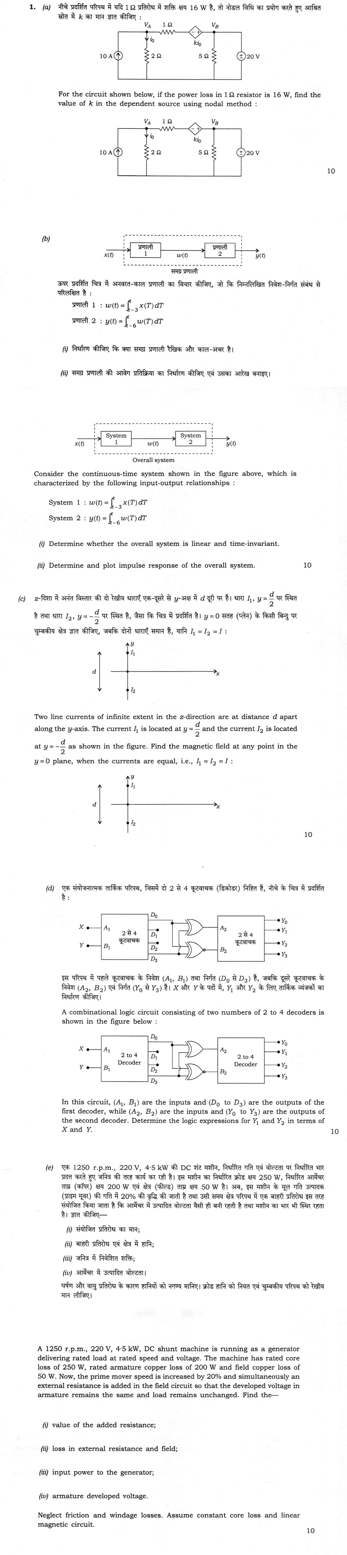
(a) For the circuit shown below, if the power loss in 1 Ω resistor is 16 W, find the value of k in the dependent source using…
For the circuit shown below, if the power loss in 1 Ω resistor is 16 W, find the value of k in the dependent source using nodal method : 10 marks
Consider the continuous-time system shown in the figure above, which is characterized by the following input-output relationships :
System 1 : w(t) = ∫ₜ₋₃^t x(T) dT System 2 : y(t) = ∫ₜ₋₆^t w(T) dT
Determine whether the overall system is linear and time-invariant.
Determine and plot impulse response of the overall system. 10 marks
Two line currents of infinite extent in the z-direction are at distance d apart along the y-axis. The current I₁ is located at y = d/2 and the current I₂ is located at y = -d/2 as shown in the figure. Find the magnetic field at any point in the y = 0 plane, when the currents are equal, i.e., I₁ = I₂ = I : 10 marks
A combinational logic circuit consisting of two numbers of 2 to 4 decoders is shown in the figure below :
[Figure : 2 to 4 Decoder with inputs X → A₁, Y → B₁, outputs D₀, D₁, D₂, D₃; OR gates; 2 to 4 Decoder with inputs A₂, B₂ and outputs Y₀, Y₁, Y₂, Y₃]
In this circuit, (A₁, B₁) are the inputs and (D₀ to D₃) are the outputs of the first decoder, while (A₂, B₂) are the inputs and (Y₀ to Y₃) are the outputs of the second decoder. Determine the logic expressions for Y₁ and Y₂ in terms of X and Y. 10 marks
A 1250 r.p.m., 220 V, 4·5 kW, DC shunt machine is running as a generator delivering rated load at rated speed and voltage. The machine has rated core loss of 250 W, rated armature copper loss of 200 W and field copper loss of 50 W. Now, the prime mover speed is increased by 20% and simultaneously an external resistance is added in the field circuit so that the developed voltage in armature remains the same and load remains unchanged. Find the—
value of the added resistance;
loss in external resistance and field;
input power to the generator;
armature developed voltage.
Neglect friction and windage losses. Assume constant core loss and linear magnetic circuit. 10 marks
हिंदी में प्रश्न पढ़ें
नीचे प्रदर्शित परिपथ में यदि 1 Ω प्रतिरोध में शक्ति क्षय 16 W है, तो नोडल विधि का प्रयोग करते हुए आश्रित स्रोत में k का मान ज्ञात कीजिए : (10 अंक)
ऊपर प्रदर्शित चित्र में अनवरत-काल प्रणाली का विचार कीजिए, जो कि निम्नलिखित निवेश-निर्गत संबंध से परिलक्षित है : प्रणाली 1 : w(t) = ∫ₜ₋₃^t x(T) dT प्रणाली 2 : y(t) = ∫ₜ₋₆^t w(T) dT निर्धारण कीजिए कि क्या समग्र प्रणाली रैखिक और काल-अचर है।
समग्र प्रणाली की आवेग प्रतिक्रिया का निर्धारण कीजिए एवं उसका आरेख बनाइए। (10 अंक)
z-दिशा में अनंत विस्तार की दो रेखीय धाराएँ एक-दूसरे से y-अक्ष में d दूरी पर हैं। धारा I₁, y = d/2 पर स्थित है तथा धारा I₂, y = -d/2 पर स्थित है, जैसा कि चित्र में प्रदर्शित है। y = 0 सतह (प्लेन) के किसी बिंदु पर चुम्बकीय क्षेत्र ज्ञात कीजिए, जबकि दोनों धाराएँ समान हैं, यानि I₁ = I₂ = I : (10 अंक)
एक संयोजनात्मक तार्किक परिपथ, जिसमें दो 2 से 4 कूटवाचक (डिकोडर) निहित हैं, नीचे के चित्र में प्रदर्शित है :
[चित्र : X → A₁, Y → B₁ निवेश वाला 2 से 4 कूटवाचक, निर्गत D₀, D₁, D₂, D₃; OR द्वार; A₂, B₂ निवेश तथा Y₀, Y₁, Y₂, Y₃ निर्गत वाला 2 से 4 कूटवाचक]
इस परिपथ में पहले कूटवाचक के निवेश (A₁, B₁) तथा निर्गत (D₀ से D₃) हैं, जबकि दूसरे कूटवाचक के निवेश (A₂, B₂) एवं निर्गत (Y₀ से Y₃) हैं। X और Y के पदों में, Y₁ और Y₂ के लिए तार्किक व्यंजकों का निर्धारण कीजिए। (10 अंक)
एक 1250 r.p.m., 220 V, 4·5 kW की DC शंट मशीन, निर्धारित गति एवं वोल्टता पर निर्धारित भार प्रदत्त करते हुए जनित्र की तरह कार्य कर रही है। इस मशीन का निर्धारित क्रोड क्षय 250 W, निर्धारित आर्मेचर ताम्र (कॉपर) क्षय 200 W एवं क्षेत्र (फील्ड) ताम्र क्षय 50 W है। अब, इस मशीन के मूल गति उत्पादक (प्राइम मूवर) की गति में 20% की वृद्धि की जाती है तथा उसी समय क्षेत्र परिपथ में एक बाहरी प्रतिरोध इस तरह संयोजित किया जाता है कि आर्मेचर में उत्पादित वोल्टता वैसी ही बनी रहती है तथा मशीन का भार भी स्थिर रहता है। ज्ञात कीजिए—
संयोजित प्रतिरोध का मान;
बाहरी प्रतिरोध एवं क्षेत्र में हानि;
जनित्र में निवेशित शक्ति;
आर्मेचर में उत्पादित वोल्टता।
घर्षण और वायु प्रतिरोध के कारण हानियों को नगण्य मानिए। क्रोड हानि को नियत एवं चुम्बकीय परिपथ को रेखीय मान लीजिए। (10 अंक)
Model answer
Drafted with AI by UPSC Answer Check against this question's marking rubric, to the expected length. UPSC does not publish answers for Mains — this is one way to score well, not an official key. How we build rubrics and answers.
(a) Nodal analysis with a dependent source (10 marks)
The ideal 20 V source is connected directly across node B, so V_B = 20 V and the 5 Ω resistor plays no part in the nodal equation. Let I be the current through the 1 Ω resistor from A towards the dependent source, and i₀ = V_A/2 the current in the 2 Ω resistor.
The power loss in the 1 Ω resistor is I² × 1 = 16 W, so |I| = 4 A. Taking I = +4 A (from A to B):
Node A (KCL): 10 = V_A/2 + I, so V_A/2 = 6 and V_A = 12 V, i₀ = 6 A.
The dependent source is drawn with its negative terminal on the 1 Ω side and its positive terminal towards B. The voltage at its left terminal is V_A − 1 × I = 12 − 4 = 8 V, so
V_B = (V_A − I) + k i₀, that is 20 = 8 + 6k, giving k = 2.
In general form, with the source voltage k i₀ = k V_A/2, the node-A equation is V_A/2 + (V_A − V_x) = 10 with V_x = 20 − kV_A/2, that is V_A (3 + k)/2 = 30. For k = 2 this gives V_A = 12 V, and the loss in 1 Ω is (12 − 8)² = 16 W, as required.
The reversed direction I = −4 A (current from B to A) also gives 16 W and leads to V_A = 28 V, i₀ = 14 A and k = −6/7. The intended, physically natural solution, with the 10 A source feeding current towards B, is k = 2.
(b) Cascaded moving-window integrators (10 marks)
System 1 is w(t) = ∫ x(τ) dτ over [t − 3, t] and System 2 is y(t) = ∫ w(τ) dτ over [t − 6, t].
(i) Linearity and time-invariance. Each system is an integral of the input over a window that moves with t, so each obeys superposition and each shifts with the input: replacing x(τ) by x(τ − t₀) shifts the output by t₀. Both stages are therefore linear and time-invariant, and so is their cascade. A cascade of LTI systems is LTI, and the order of the two stages does not matter.
(ii) Impulse response. Put x(t) = δ(t). For System 1, h₁(t) = ∫ δ(τ) dτ over [t − 3, t] = 1 for 0 ≤ t ≤ 3, so h₁(t) = u(t) − u(t − 3), a rectangular pulse of height 1 and width 3. Likewise h₂(t) = u(t) − u(t − 6), a rectangle of width 6. The overall impulse response is the convolution
h(t) = h₁(t) * h₂(t) = ∫ h₁(τ) h₂(t − τ) dτ.
Convolving the two rectangles gives a trapezoid:
- h(t) = 0 for t < 0 and t > 9;
- h(t) = t for 0 ≤ t ≤ 3 (rising);
- h(t) = 3 for 3 ≤ t ≤ 6 (flat);
- h(t) = 9 − t for 6 ≤ t ≤ 9 (falling).
The base width is 3 + 6 = 9 s, the flat top has height equal to the shorter width, 3, and the area is 3 × 6 = 18, equal to the product of the areas of the two rectangles.

(c) Magnetic field of two equal line currents (10 marks)
Taking both currents I as equal and in the same direction, out of the page (+z), as the dots in the figure show, use Ampere's law for an infinite line current: B = μ₀I/(2πr) in the circumferential direction. A point P at (x, 0) is at distance r = √(x² + d²/4) from each wire, and the line from each wire to P makes an angle θ with the x-axis, where sin θ = (d/2)/r and cos θ = x/r.
Each field is perpendicular to the line joining that wire to P. The two fields have equal magnitude, μ₀I/(2πr). Their y-components add, since the wires are symmetric about y = 0, while their x-components, ±(μ₀I/2πr) sin θ, are equal and opposite and cancel. The resultant is
B = 2 × μ₀I/(2πr) × cos θ = μ₀I x/(π r²) = μ₀ I x/(π (x² + d²/4)) = 4μ₀ I x/(π (4x² + d²)),
directed along +y for x > 0 and along −y for x < 0 (the field lies wholly in the plane, perpendicular to the line joining the wires).
Checks: B = 0 at x = 0, midway between the wires, where the two fields are equal and opposite; and for x ≫ d, B → μ₀(2I)/(2πx), the field of a single wire carrying 2I. The magnitude is greatest at x = ±d/2, where B_max = μ₀I/(πd). If the currents were opposite, the y-components would cancel and the field would be along x.
(d) Combinational logic with two decoders (10 marks)
Take A₁ (= X) as the most significant input and active-high outputs, so the first decoder gives D₀ = X′Y′, D₁ = X′Y, D₂ = XY′ and D₃ = XY.
In the figure only D₀ and D₃ are connected: both go to the two gates, with D₁ and D₂ left open. The upper gate is an XOR and the lower is an XNOR (a bubble on its output). The inputs to the second decoder are
A₂ = D₀ ⊕ D₃ and B₂ = (D₀ ⊕ D₃)′.
D₀ and D₃ can never be 1 together, so D₀ ⊕ D₃ = D₀ + D₃ = X′Y′ + XY, that is A₂ = X ⊙ Y (XNOR) and B₂ = X ⊕ Y (XOR), the complement of A₂.
The second decoder outputs are then Y₀ = A₂′B₂′, Y₁ = A₂′B₂, Y₂ = A₂B₂′ and Y₃ = A₂B₂:
- Y₁ = A₂′B₂ = (X ⊕ Y)(X ⊕ Y) = X ⊕ Y = XY′ + X′Y;
- Y₂ = A₂B₂′ = (X ⊙ Y)(X ⊙ Y) = X ⊙ Y = XY + X′Y′.
Since A₂ and B₂ are always complementary, Y₀ = Y₃ = 0 and only Y₁ or Y₂ can be high: Y₁ = 1 when X ≠ Y and Y₂ = 1 when X = Y.
(e) DC shunt generator with a higher speed and added field resistance (10 marks)
Rated data. Rated output current I_L = 4500/220 = 20.45 A. Field current I_f = P_f/V = 50/220 = 0.2273 A, so the field resistance is R_f = 220/0.2273 = 968 Ω. Armature current I_a = 20.45 + 0.227 = 20.68 A, so R_a = 200/20.68² = 0.4676 Ω and the generated emf is E = 220 + 20.68 × 0.4676 = 229.67 V.
(i) Added resistance. At 1.2 N the emf must remain 229.67 V. With a linear magnetic circuit, E ∝ Nφ ∝ N I_f, so the flux, and hence I_f, must fall to 1/1.2 of its value: I_f′ = 0.2273/1.2 = 0.1894 A. The terminal voltage stays 220 V, so the total field-circuit resistance is 220/0.1894 = 1161.6 Ω, and the added resistance is 1161.6 − 968 = 193.6 Ω.
(ii) Loss in the external resistance and field. Field-circuit loss = V I_f′ = 220 × 0.1894 = 41.7 W, made up of 0.1894² × 968 = 34.7 W in the field winding and 0.1894² × 193.6 = 6.9 W in the external resistance (before the change the field loss was 50 W).
(iii) Input power. The load is unchanged, so the output is 4500 W at 220 V and I_L = 20.45 A. The armature current is I_a′ = 20.45 + 0.189 = 20.64 A, and the armature copper loss is 20.64² × 0.4676 = 199.3 W. The core loss is constant at 250 W, and friction and windage are neglected. Then
P_in = 4500 + 199.3 + 41.7 + 250 = 4991 W ≈ 4.99 kW.
(iv) Armature developed voltage. E′ = V + I_a′ R_a = 220 + 20.64 × 0.4676 = 229.65 V ≈ 229.7 V, the same as before, as the problem requires.
How this answer will be evaluated
What earns full marks: Complete method with correct results and clear interpretation
Evaluation rubric
Each sub-part is marked on its own, against the marks and word limit printed on the paper.
- (a) Find k in the dependent source of the circuit by nodal analysis, given that the power loss in the 1 Ω resistor is 16 W. 10 marks
calculate— given → formula → substitution → result with units → interpretation
Must cover
- V_B = 20 V fixed by the ideal source; the 5 Ω resistor does not enter the nodal equation
- Power 16 W in 1 Ω gives |I| = 4 A; KCL at A: 10 = V_A/2 + I, so V_A = 12 V and i₀ = 6 A
- Dependent-source equation with the polarity as drawn: 20 = (V_A − I) + k i₀
- k = 2, with the check that the loss in 1 Ω is 16 W
Loses marks
- Ignoring the polarity of the dependent source.
- Treating the 5 Ω resistor as carrying part of the 10 A.
- Using 16 A or 16 V for the 1 Ω resistor instead of 16 W.
Earns more
- Noting the second current direction I = −4 A gives k = −6/7 and explaining which is intended.
- Writing the general nodal equation V_A(3 + k)/2 = 30.
Extra mark
- Independent verification of the power balance of the whole circuit
- (b) Determine whether the cascade of two moving-window integrators is linear and time-invariant, and find and plot its impulse response. 10 marks
analyse— intro → causes → effects → stakeholders/linkages → way forward
Must cover
- Both stages are linear and time-invariant, so the cascade is LTI
- h₁(t) = u(t) − u(t − 3) and h₂(t) = u(t) − u(t − 6)
- h = h₁ * h₂ is a trapezoid: t on 0 to 3, 3 on 3 to 6, 9 − t on 6 to 9, zero outside
- Plot with labelled breakpoints 0, 3, 6, 9 and peak 3
Loses marks
- Stating that the system is time-varying because the limits depend on t.
- Plotting a triangle or rectangle instead of a trapezoid.
- Wrong base width, such as 6 or 18.
Earns more
- Area check: total area 3 × 6 = 18.
- Justification of linearity and time-invariance from the integral form.
Extra mark
- Observing that the overall response is causal and finite-duration (FIR-like), so the system is BIBO stable
- (c) Find the magnetic field at any point of the y = 0 plane for two equal line currents I at y = ±d/2. 10 marks
calculate— given → formula → substitution → result with units → interpretation
Must cover
- B = μ₀I/(2πr) for each wire with r = √(x² + d²/4)
- Vector addition: components along x cancel by symmetry
- B = μ₀I x/(π(x² + d²/4)), directed along y (sign follows x)
- Checks: B = 0 at x = 0 and B → μ₀(2I)/(2πx) at large x
Loses marks
- Adding the magnitudes of the two fields without resolving them.
- Giving a field along x, or a non-zero field at x = 0.
- Using the distance d/2 in place of r for points off the y-axis.
Earns more
- Stating the assumption that both currents flow in +z.
- Geometric explanation with the angle θ, sin θ = d/2r and cos θ = x/r.
Extra mark
- Location of the maximum field at x = ±d/2, with B_max = μ₀I/(πd)
- (d) Find the logic expressions for Y₁ and Y₂ of the combinational circuit made of two 2-to-4 decoders and an XOR and XNOR gate. 10 marks
calculate— given → formula → substitution → result with units → interpretation
Must cover
- First decoder: D₀ = X′Y′, D₃ = XY; only D₀ and D₃ are connected, D₁ and D₂ are open
- A₂ = D₀ ⊕ D₃ = X ⊙ Y (XNOR); B₂ = its complement = X ⊕ Y
- Second decoder: Y₁ = A₂′B₂ and Y₂ = A₂B₂′
- Y₁ = X ⊕ Y = XY′ + X′Y and Y₂ = X ⊙ Y = XY + X′Y′; Y₀ = Y₃ = 0
Loses marks
- Interchanging the XOR and XNOR gates, which gives Y₁ and Y₂ swapped.
- Connecting D₁ and D₂ to the gates.
- Leaving the answer in terms of A₂ and B₂ and not X and Y.
Earns more
- Stating the convention that A is the MSB and outputs are active high.
- Explaining that D₀ and D₃ are mutually exclusive, so the XOR reduces to an OR.
Extra mark
- Remark that the circuit works as an equality detector: Y₁ for X ≠ Y, Y₂ for X = Y
- (e) For a DC shunt generator (1250 rpm, 220 V, 4.5 kW; core loss 250 W, armature copper loss 200 W, field copper loss 50 W) with the speed raised by 20% and a resistor added in the field circuit so that the generated voltage and load remain unchanged, find (i) the added resistance, (ii) the loss in the external resistance and field, (iii) the input power and (iv) the developed armature voltage. 10 marks
calculate— given → formula → substitution → result with units → interpretation
Must cover
- Rated: I_L = 20.45 A, I_f = 0.2273 A, R_f = 968 Ω, I_a = 20.68 A, R_a = 0.4676 Ω, E = 229.67 V
- Flux and I_f fall by 1/1.2: I_f′ = 0.1894 A; total field resistance 1161.6 Ω, added resistance = 193.6 Ω
- Field-circuit loss = 220 × 0.1894 = 41.7 W (34.7 W in field, 6.9 W in the external resistor)
- Input = 4500 + 199.3 + 41.7 + 250 ≈ 4991 W; developed voltage ≈ 229.7 V
Loses marks
- Keeping the flux constant and reducing the emf instead of holding E fixed.
- Omitting the core loss from the input power.
- Using the old field loss of 50 W in the input power.
Earns more
- Use of the linear magnetic circuit condition E ∝ N I_f.
- Recomputing the armature copper loss with the new armature current.
Extra mark
- Verification of the power balance E I_a′ = output + armature loss + field loss
What "Solve" is asking you to do
Choose the method, then carry it through to a final answer. Identifying what kind of problem this is and why that method applies is the first thing marked; a correct figure arrived at invisibly earns almost nothing.
Structure that answers it
Given data and what is required → method chosen, with the reason it applies → set-up (equation, circuit, free body, trial balance) → working, step by step → answer with units and any condition of validity
Where marks are lost
Doing the middle steps mentally and writing only the result. In mathematics papers, a further loss comes from giving a decimal where the exact value in surds or fractions was wanted, or from skipping the justification a part explicitly asks for.
Practice this exact question
Write your answer and it is marked point by point against the model answer above — what you covered, what you missed, what you got wrong.
Evaluate my answer →More from Electrical Engineering 2026 Paper I
- Q1 (a) For the circuit shown below, if the power loss in 1 Ω resistor is 16 W, find the valu…
- Q2 (a) (i) Find the values of R and C in the figure shown below, so that V_b = 3V_a, also V̄…
- Q3 (a) (i) For the circuit shown below, steady state is achieved with switch K open. At t =…
- Q4 (a) (i) The continuous-time signal x(t) = cos(20πt + π/4) is ideally sampled at a rate of…