Paper I — Q4
(a) (i) The continuous-time signal x(t) = cos(20πt + π/4) is ideally sampled at a rate of 30 samples per second. The resulting…
The continuous-time signal x(t) = cos(20πt + π/4) is ideally sampled at a rate of 30 samples per second. The resulting sampled signal is then passed through a filter whose impulse response is h(t) = sin(πt)/πt · cos(80πt − π/2). Find the expression for the output signal of the filter. 15 marks
A discrete-time sequence x(n) = {3, 5, 1, 4, −3, 5, −2, −2, 4} of length 9 has a 9-point DFT denoted by X(k), where k = 0, 1, 2, ..., 8. Another discrete-time sequence y(n) has a 9-point DFT given by Y(k) = e^(j4πk/3) X(k), k = 0, 1, 2, ..., 8. Without explicitly computing DFT or inverse DFT, determine the sequence y(n). 5 marks
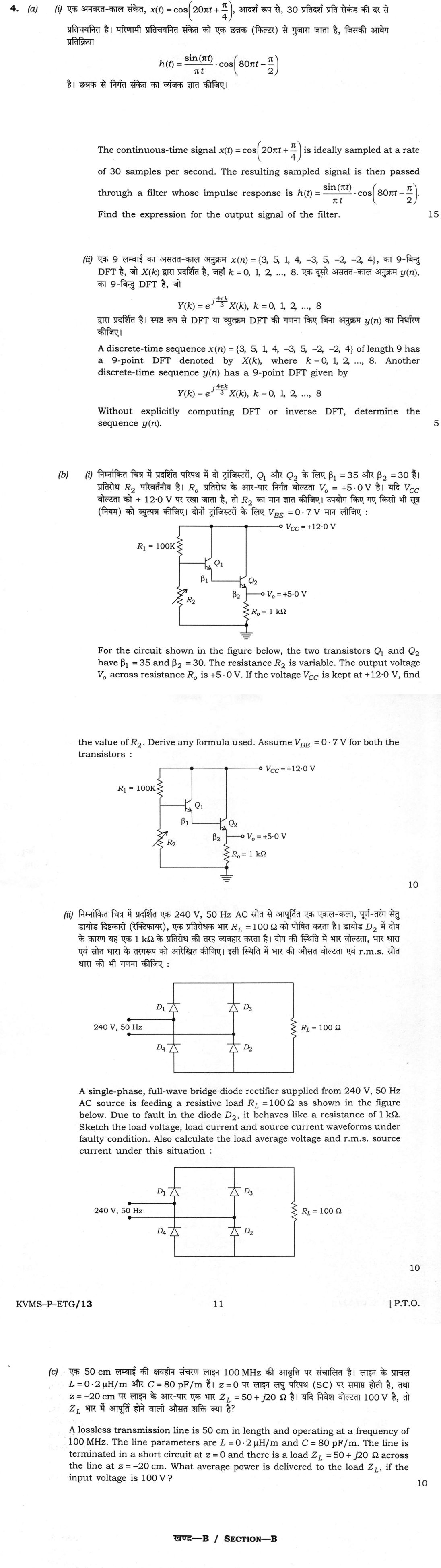
For the circuit shown in the figure below, the two transistors Q₁ and Q₂ have β₁ = 35 and β₂ = 30. The resistance R₂ is variable. The output voltage V_o across resistance R_o is +5·0 V. If the voltage V_CC is kept at +12·0 V, find the value of R_2. Derive any formula used. Assume V_BE = 0·7 V for both the transistors : 10 marks
A single-phase, full-wave bridge diode rectifier supplied from 240 V, 50 Hz AC source is feeding a resistive load R_L = 100 Ω as shown in the figure below. Due to fault in the diode D_2, it behaves like a resistance of 1 kΩ. Sketch the load voltage, load current and source current waveforms under faulty condition. Also calculate the load average voltage and r.m.s. source current under this situation : 10 marks
A lossless transmission line is 50 cm in length and operating at a frequency of 100 MHz. The line parameters are L = 0·2 μH/m and C = 80 pF/m. The line is terminated in a short circuit at z = 0 and there is a load Z_L = 50 + j20 Ω across the line at z = –20 cm. What average power is delivered to the load Z_L, if the input voltage is 100 V? 10 marks
हिंदी में प्रश्न पढ़ें
एक अनवरत-काल संकेत, x(t) = cos(20πt + π/4), आदर्श रूप से, 30 प्रतिदर्श प्रति सेकंड की दर से प्रतिचयनित है। परिणामी प्रतिचयनित संकेत को एक छन्नक (फिल्टर) से गुजारा जाता है, जिसकी आवेग प्रतिक्रिया h(t) = sin(πt)/(πt) · cos(80πt − π/2) है। छन्नक से निर्गत संकेत का व्यंजक ज्ञात कीजिए। (15 अंक)
एक 9 लम्बाई का असतत-काल अनुक्रम x(n) = {3, 5, 1, 4, −3, 5, −2, −2, 4}, का 9-बिन्दु DFT है, जो X(k) द्वारा प्रदर्शित है, जहाँ k = 0, 1, 2, ..., 8. एक दूसरे असतत-काल अनुक्रम y(n), का 9-बिन्दु DFT है, जो Y(k) = e^(j4πk/3) X(k), k = 0, 1, 2, ..., 8 द्वारा प्रदर्शित है। स्पष्ट रूप से DFT या व्युत्क्रम DFT की गणना किए बिना अनुक्रम y(n) का निर्धारण कीजिए। (5 अंक)
निम्नांकित चित्र में प्रदर्शित परिपथ में दो ट्रांजिस्टरों, Q₁ और Q₂ के लिए β₁ = 35 और β₂ = 30 हैं। प्रतिरोध R₂ परिवर्तनीय है। R_o प्रतिरोध के आर-पार निर्गत वोल्टता V_o = +5·0 V है। यदि V_CC वोल्टता को +12·0 V पर रखा जाता है, तो R₂ का मान ज्ञात कीजिए। उपयोग किए गए किसी भी सूत्र (नियम) को व्युत्पन्न कीजिए। दोनों ट्रांजिस्टरों के लिए V_BE = 0·7 V मान लीजिए : (10 अंक)
निम्नांकित चित्र में प्रदर्शित एक 240 V, 50 Hz AC स्रोत से आपूर्तित एक एकल-कला, पूर्ण-तरंग सेतु डायोड दिष्टकारी (रेक्टिफायर), एक प्रतिरोधक भार R_L = 100 Ω को पोषित करता है। डायोड D_2 में दोष के कारण यह एक 1 kΩ के प्रतिरोध की तरह व्यवहार करता है। दोष की स्थिति में भार वोल्टता, भार धारा एवं स्रोत धारा के तरंगरूप को आरेखित कीजिए। इसी स्थिति में भार की औसत वोल्टता एवं r.m.s. स्रोत धारा की भी गणना कीजिए : (10 अंक)
एक 50 cm लम्बाई की क्षयहीन संचरण लाइन 100 MHz की आवृत्ति पर संचालित है। लाइन के प्राचल L = 0·2 μH/m और C = 80 pF/m हैं। z = 0 पर लाइन लघु परिपथ (SC) पर समाप्त होती है, तथा z = –20 cm पर लाइन के आर-पार एक भार Z_L = 50 + j20 Ω है। यदि निवेश वोल्टता 100 V है, तो Z_L भार में आपूर्ति होने वाली औसत शक्ति क्या है? (10 अंक)
Model answer
Drafted with AI by UPSC Answer Check against this question's marking rubric, to the expected length. UPSC does not publish answers for Mains — this is one way to score well, not an official key. How we build rubrics and answers.
(a)(i) Sampled cosine passed through a band-pass filter (15 marks)
Spectrum of the sampled signal. x(t) = cos(20πt + π/4) has frequency f₀ = 10 Hz. Ideal sampling at fₛ = 30 Hz multiplies x(t) by an impulse train, whose Fourier series is fₛ Σₖ e^j2πk fₛ t, so the sampled spectrum repeats X(f) at every multiple of fₛ:
Xₛ(f) = fₛ Σₖ X(f − k fₛ), with X(f) = ½[e^jπ/4 δ(f − 10) + e^−jπ/4 δ(f + 10)].
The spectral lines therefore lie at f = ±10 + 30k Hz, that is 10, 20, 40, 50, 70, 80 … Hz and their negatives; the one at +40 Hz comes from k = 1 (10 + 30) and has weight fₛ × ½ e^jπ/4 = 15 e^jπ/4.
The filter. Since sin(πt)/(πt) has transform rect(f) (unit height, |f| < 0.5 Hz), and cos(80πt − π/2) = ½[e^−jπ/2 e^j2π40t + e^jπ/2 e^−j2π40t], modulation shifts the rectangle to ±40 Hz:
H(f) = ½ e^−jπ/2 rect(f − 40) + ½ e^jπ/2 rect(f + 40).
It is a narrow band-pass filter with pass band 39.5–40.5 Hz (and its mirror image), gain 1/2 and phase −90° at +40 Hz (H(40) = ½ e^−jπ/2 = −j/2), and the opposite phase at −40 Hz.
Output. Only the ±40 Hz lines fall in the pass band, and no other line (20, 50 Hz …) does. The component at +40 Hz, 15 e^j(80πt + π/4), is multiplied by H(40), and the −40 Hz component by H(−40) = H(40)*. Their sum is
y(t) = 2 Re15 e^j(80πt + π/4) × ½ e^−jπ/2 = 15 cos(80πt − π/4).
The 10 Hz signal has thus been aliased to 40 Hz (= 30 + 10) by the sampling and picked out by the filter, with amplitude 15 = 30 × ½ (line weight) × ½ (filter gain) × 2 (conjugate pair) and phase π/4 − π/2 = −π/4.
(a)(ii) Circular shift by the DFT property (5 marks)
N = 9, and e^j4πk/3 = e^j2πk·6/9. By the circular time-shift property, x((n + m))_N ↔ e^j2πkm/N X(k), so here m = 6 and
y(n) = x((n + 6))₉ = x((n − 3))₉,
a circular right shift of x(n) by 3 samples (the same as a left shift by 6). Shifting 3, 5, 1, 4, −3, 5, −2, −2, 4 right by 3, the last three samples move to the front:
y(n) = −2, −2, 4, 3, 5, 1, 4, −3, 5.
(b)(i) Bias of a Darlington emitter follower (10 marks)
Derivation of the relations. For the pair, the emitter current of Q₁ is the base current of Q₂: I_B2 = I_E1 = (1 + β₁) I_B1. The output current is I_E2 = (1 + β₂) I_B2, so
I_E2 = (1 + β₁)(1 + β₂) I_B1.
The base of Q₁ is one V_BE for Q₁ and one for Q₂ above the output: V_B1 = Vₒ + 2V_BE.
Numbers.
- I_E2 = Vₒ/Rₒ = 5.0/1 kΩ = 5.0 mA.
- I_B1 = I_E2/[(1 + β₁)(1 + β₂)] = 5 mA/(36 × 31) = 4.48 μA.
- V_B1 = 5.0 + 2 × 0.7 = 6.4 V.
- Current in R₁: I_R1 = (V_CC − V_B1)/R₁ = (12 − 6.4)/100 kΩ = 56 μA.
- Current in R₂: I_R2 = I_R1 − I_B1 = 56 − 4.48 = 51.52 μA.
Then
R₂ = V_B1/I_R2 = 6.4/51.52 μA ≈ 124 kΩ.
In general form, R₂ = (Vₒ + 2V_BE)/[V_CC − Vₒ − 2V_BE]/R₁ − Vₒ/[Rₒ(1 + β₁)(1 + β₂)].
(b)(ii) Bridge rectifier with a faulty diode (10 marks)
The bridge is the standard one, with D₁ and D₃ tied to the positive rail and D₂ and D₄ to the negative rail. D₂ behaves as a 1 kΩ resistor in both directions. The supply is vₛ = Vₘ sin ωt with Vₘ = 240√2 = 339.4 V.
Positive half-cycle (upper terminal positive). The path is D₁ → R_L → the faulty D₂ (1 kΩ), so the series resistance is 100 + 1000 = 1100 Ω. i_L = vₛ/1100 (peak 0.309 A) and v_L = vₛ/11 (peak 30.9 V); the source current equals i_L.
Negative half-cycle. The path is D₃ → R_L → D₄, both ideal, so v_L = |vₛ| (peak 339.4 V) and i_L = |vₛ|/100 (peak 3.39 A). In addition the 1 kΩ resistance of D₂ connects the negative rail directly to the lower supply terminal, so it carries |vₛ|/1000, and the source supplies iₛ = −|vₛ| (1/100 + 1/1000) = −|vₛ|/90.9 (peak −3.73 A).
Waveforms. The output is strongly unbalanced: a small hump (30.9 V) in one half-cycle and a full 339.4 V hump in the other. The source current is asymmetric, small and positive (0.31 A peak) in one half-cycle and large and negative (3.73 A peak) in the other, so the supply current has a large dc component.

Average load voltage.
V_L(avg) = (1/2π)[∫₀^π (Vₘ/11) sin θ dθ + ∫_π²π Vₘ |sin θ| dθ] = (Vₘ/2π)(2/11 + 2) = (Vₘ/π)(12/11) = (339.4/π)(12/11) ≈ 117.9 V.
RMS source current. The positive half-cycle has peak 0.3086 A and the negative half-cycle has peak 3.7335 A. Each half-cycle is a half-sine whose mean square over the full period is (peak)²/4, so
Iₛ(rms) = √¼ [0.3086² + 3.7335²] = √¼ (0.0952 + 13.939) = √3.509 ≈ 1.87 A.
(c) Average power delivered to the load on a shorted line (10 marks)
Line constants. Z₀ = √(L/C) = √(0.2 × 10⁻⁶/80 × 10⁻¹²) = 50 Ω and v = 1/√(LC) = 2.5 × 10⁸ m/s, so λ = v/f = 2.5 m and β = 2π/λ = 2.513 rad/m.
Circuit. The load Z_L = 50 + j20 Ω is shunted across the line at z = −20 cm. The section from z = −20 cm to the short at z = 0 is a shorted stub of length 0.2 m = 0.08λ (βℓ = 28.8°):
Z_stub = jZ₀ tan βℓ = j50 tan 28.8° = j27.5 Ω.
At the junction the stub is in parallel with Z_L:
Zⱼ = Z_L Z_stub/(Z_L + Z_stub) = (50 + j20)(j27.5)/(50 + j47.5) = 7.94 + j19.9 Ω.
The section from the junction to the input, z = −50 cm, is 0.3 m = 0.12λ (βℓ = 43.2°, tan = 0.94), so
Z_in = Z₀ (Zⱼ + jZ₀ tan βℓ)/(Z₀ + jZⱼ tan βℓ) = 50 (7.94 + j66.9)/(31.3 + j7.5) ≈ 36.2 + j98.3 Ω.
Power. The line is lossless and the short and the stub absorb no power, so all the real power at the input, taking 100 V as an r.m.s. value, reaches Z_L:
P = |V_in|² Re(Z_in)/|Z_in|² = 100² × 36.2/(36.2² + 98.3²) = 362 000/10 974 ≈ 32.9 W.
Check by the load voltage: V_L = V_in/[cos βℓ + j(Z₀/Zⱼ) sin βℓ] gives |V_L| = 43.7 V, and P = |V_L|² Re(1/Z_L) = 43.7² × 50/2900 = 32.9 W. If 100 V were a peak value, the power would be half, 16.5 W.
How this answer will be evaluated
Evaluation rubric
Each sub-part is marked on its own, against the marks and word limit printed on the paper.
- (a)(i) Find the output of the filter h(t) = [sin(πt)/(πt)]cos(80πt − π/2) when x(t) = cos(20πt + π/4) is ideally sampled at 30 samples/s and the impulse train is filtered. 15 marks
Must cover
- f₀ = 10 Hz, f_s = 30 Hz; X_s(f) = f_s ΣX(f − kf_s), lines at ±10 + 30k Hz
- sinc ↔ rect; h(t) is a narrow band-pass filter, pass band 39.5–40.5 Hz
- H(40) = ½ e^(−jπ/2), gain ½ and phase −90°; only the 40 Hz line (k = 1) survives
- y(t) = 15 cos(80πt − π/4)
Loses marks
- Ignoring the sampling and filtering x(t) directly.
- Omitting the factor f_s or the filter gain ½ in the amplitude.
- Wrong phase, such as +π/4 or −3π/4.
Earns more
- Line weight f_s/2 = 15 at +40 Hz and the conjugate component at −40 Hz.
- Recognising cos(80πt − π/2) = sin(80πt).
Extra mark
- Noting the aliasing of the 10 Hz component to 40 Hz
- (a)(ii) Find y(n) for Y(k) = e^(j4πk/3) X(k) without computing the DFT or inverse DFT. 5 marks
Must cover
- N = 9 and e^(j4πk/3) = e^(j2πk·6/9)
- Circular time-shift property of the DFT
- y(n) = x((n − 3)) mod 9 (equivalently x((n + 6)) mod 9)
- y(n) = {−2, −2, 4, 3, 5, 1, 4, −3, 5}
Loses marks
- Applying a linear shift with zero fill.
- Shifting left by 3 instead of right by 3.
- Computing the DFT explicitly.
Earns more
- Stating the direction of the shift: circular right shift by 3.
Extra mark
- Observation that the shift is circular, so samples wrap around
- (b)(i) Find R₂ for the Darlington emitter follower with V_o = 5 V, R_o = 1 kΩ, V_CC = 12 V, R₁ = 100 kΩ, β₁ = 35, β₂ = 30, V_BE = 0.7 V, deriving the formula used. 10 marks
Must cover
- Derivation I_E2 = (1 + β₁)(1 + β₂)I_B1 and V_B1 = V_o + 2V_BE
- I_E2 = 5 mA, I_B1 = 4.48 μA, V_B1 = 6.4 V
- I_R1 = 56 μA and I_R2 = I_R1 − I_B1 = 51.5 μA
- R₂ = 6.4/51.5 μA ≈ 124 kΩ
Loses marks
- Taking V_B1 = V_o + V_BE (one drop only).
- Using β₁β₂ in place of (1 + β₁)(1 + β₂), or ignoring I_B1 in R₂.
- Using the full 12 V across R₂.
Earns more
- General formula for R₂ in terms of the circuit values.
Extra mark
- Check that the divider current is more than 10 times I_B1 for stiff biasing
- (b)(ii) Sketch v_L, i_L and i_s when diode D₂ of a 240 V, 50 Hz full-wave bridge with R_L = 100 Ω has failed to a 1 kΩ resistance, and find the average load voltage and rms source current. 10 marks
Must cover
- V_m = 339.4 V; positive half: 1100 Ω in the path, v_L = v_s/11 (peak 30.9 V)
- Negative half: v_L = |v_s| (peak 339.4 V) and source current |v_s|(1/100 + 1/1000), peak 3.73 A
- Three waveform sketches: unbalanced load voltage/current and asymmetric source current
- V_L(avg) ≈ 117.9 V and I_s(rms) ≈ 1.87 A
Loses marks
- Treating the bridge as fully healthy (V_avg = 0.9 × 240 = 216 V).
- Ignoring the current in the faulty diode during the negative half-cycle.
- Giving equal positive and negative half-cycles of source current.
Earns more
- Integral for the average value with the two half-cycles treated separately.
- Peak values labelled on the sketches.
Extra mark
- Comment on the dc component in the source current
- (c) Find the average power delivered to Z_L = 50 + j20 Ω, shunted across a 50 cm lossless line (L = 0.2 μH/m, C = 80 pF/m, 100 MHz) short-circuited at z = 0, at z = −20 cm, with 100 V at the input. 10 marks
Must cover
- Z₀ = 50 Ω, v = 2.5 × 10⁸ m/s, λ = 2.5 m (0.2 m = 0.08λ and 0.3 m = 0.12λ)
- Shorted stub Z = j50 tan 28.8° = j27.5 Ω in parallel with Z_L: Z_j = 7.94 + j19.9 Ω
- Z_in = 36.2 + j98.3 Ω by transforming through 0.12λ
- P = |V|²Re(Z_in)/|Z_in|² ≈ 32.9 W (100 V taken as r.m.s.)
Loses marks
- Omitting the shorted stub and using Z_L alone.
- Wrong electrical lengths, such as 0.2λ and 0.3λ.
- Reporting Z_in without the power.
Earns more
- Stating that the lossless line and stub absorb no power.
- Cross-check through the load voltage |V_L| = 43.7 V.
Extra mark
- Mention that a peak value for 100 V gives 16.5 W
What "Solve" is asking you to do
Choose the method, then carry it through to a final answer. Identifying what kind of problem this is and why that method applies is the first thing marked; a correct figure arrived at invisibly earns almost nothing.
Structure that answers it
Given data and what is required → method chosen, with the reason it applies → set-up (equation, circuit, free body, trial balance) → working, step by step → answer with units and any condition of validity
Where marks are lost
Doing the middle steps mentally and writing only the result. In mathematics papers, a further loss comes from giving a decimal where the exact value in surds or fractions was wanted, or from skipping the justification a part explicitly asks for.
Practice this exact question
Write your answer and it is marked point by point against the model answer above — what you covered, what you missed, what you got wrong.
Evaluate my answer →More from Electrical Engineering 2026 Paper I
- Q1 (a) For the circuit shown below, if the power loss in 1 Ω resistor is 16 W, find the valu…
- Q2 (a) (i) Find the values of R and C in the figure shown below, so that V_b = 3V_a, also V̄…
- Q3 (a) (i) For the circuit shown below, steady state is achieved with switch K open. At t =…
- Q4 (a) (i) The continuous-time signal x(t) = cos(20πt + π/4) is ideally sampled at a rate of…
- Q5 (a) For the circuit given in the figure below, the input voltage signal is given by V_in…
- Q6 (a) Design a MOD-6 synchronous DOWN counter using J-K flip-flops. (20 marks) (b) A three-…
- Q7 (a) Design a Programmable Logic Array (PLA) for a combinational logic circuit that comput…