Paper I — Q6
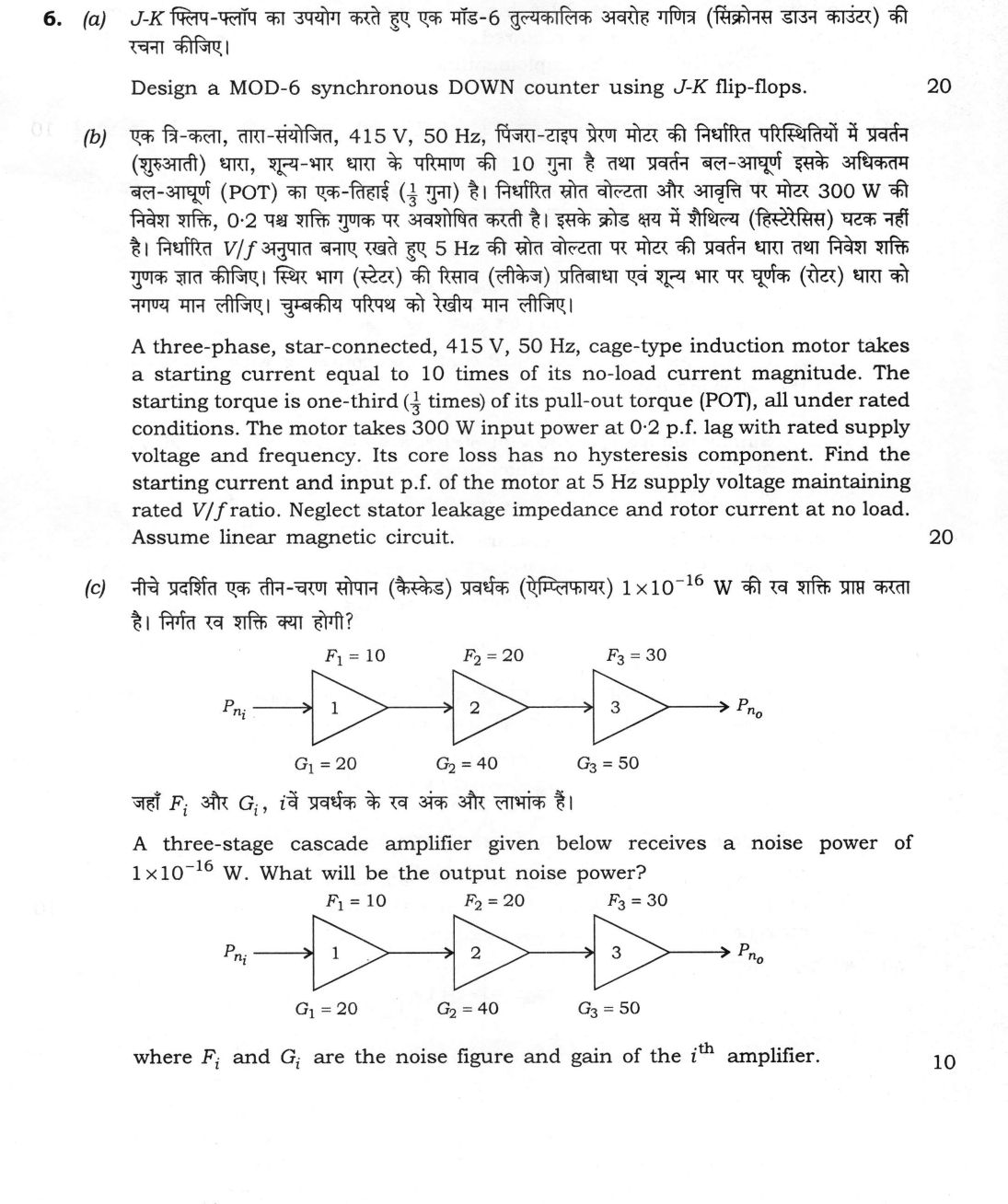
(a) Design a MOD-6 synchronous DOWN counter using J-K flip-flops. (20 marks) (b) A three-phase, star-connected, 415 V, 50 Hz…
Design a MOD-6 synchronous DOWN counter using J-K flip-flops. 20 marks
A three-phase, star-connected, 415 V, 50 Hz, cage-type induction motor takes a starting current equal to 10 times of its no-load current magnitude. The starting torque is one-third (1/3 times) of its pull-out torque (POT), all under rated conditions. The motor takes 300 W input power at 0·2 p.f. lag with rated supply voltage and frequency. Its core loss has no hysteresis component. Find the starting current and input p.f. of the motor at 5 Hz supply voltage maintaining rated V/f ratio. Neglect stator leakage impedance and rotor current at no load. Assume linear magnetic circuit. 20 marks
A three-stage cascade amplifier given below receives a noise power of 1×10⁻¹⁶ W. What will be the output noise power? (Diagram: Pₙᵢ → 1 → 2 → 3 → Pₙₒ, with F₁ = 10, F₂ = 20, F₃ = 30; G₁ = 20, G₂ = 40, G₃ = 50) where Fᵢ and Gᵢ are the noise figure and gain of the iᵗʰ amplifier. 10 marks
हिंदी में प्रश्न पढ़ें
J-K फ्लिप-फ्लॉप का उपयोग करते हुए एक मॉड-6 तुल्यकालिक अवरोह गणित्र (सिंक्रोनस डाउन काउंटर) की रचना कीजिए। (20 अंक)
एक त्रि-कला, तारा-संयोजित, 415 V, 50 Hz, पिंजरा-टाइप प्रेरण मोटर की निर्धारित परिस्थितियों में प्रवर्तन (शुरुआती) धारा, शून्य-भार धारा के परिमाण की 10 गुना है तथा प्रवर्तन बल-आघूर्ण इसके अधिकतम बल-आघूर्ण (POT) का एक-तिहाई (1/3 गुना) है। निर्धारित स्रोत वोल्टता और आवृत्ति पर मोटर 300 W की निवेश शक्ति, 0·2 पश्च शक्ति गुणक पर अवशोषित करती है। इसके क्रोड क्षय में शैथिल्य (हिस्टेरेसिस) घटक नहीं है। निर्धारित V/f अनुपात बनाए रखते हुए 5 Hz की स्रोत वोल्टता पर मोटर की प्रवर्तन धारा तथा निवेश शक्ति गुणक ज्ञात कीजिए। स्थिर भाग (स्टेटर) की रिसाव (लीकेज) प्रतिबाधा एवं शून्य भार पर घूर्णक (रोटर) धारा को नगण्य मान लीजिए। चुम्बकीय परिपथ को रेखीय मान लीजिए। (20 अंक)
नीचे प्रदर्शित एक तीन-चरण सोपान (कैस्केड) प्रवर्धक (ऐम्प्लीफायर) 1×10⁻¹⁶ W की शक्ति प्राप्त करता है। निर्गत रव शक्ति क्या होगी? (आरेख: Pₙᵢ → 1 → 2 → 3 → Pₙₒ, जहाँ F₁ = 10, F₂ = 20, F₃ = 30; G₁ = 20, G₂ = 40, G₃ = 50) जहाँ Fᵢ और Gᵢ, iवें प्रवर्धक के रव अंक और लाभांक हैं। (10 अंक)
Model answer
Drafted with AI by UPSC Answer Check against this question's marking rubric, to the expected length. UPSC does not publish answers for Mains — this is one way to score well, not an official key. How we build rubrics and answers.
(a) Synchronous MOD-6 down counter with J-K flip-flops (20 marks)
Number of flip-flops and sequence. A MOD-6 counter has six states, so n = 3 flip-flops are needed (2³ = 8 ≥ 6). Let the state be Q₂Q₁Q₀. A down counter counts 5, 4, 3, 2, 1, 0 and then returns to 5:
101 → 100 → 011 → 010 → 001 → 000 → 101.
The states 110 and 111 are unused; their next states are treated as don't cares in the design and are checked afterwards. All flip-flops share a common clock (synchronous).
Excitation table of the J-K flip-flop. 0 → 0: J = 0, K = X; 0 → 1: J = 1, K = X; 1 → 0: J = X, K = 1; 1 → 1: J = X, K = 0.
State and excitation table.
- 101 → 100: J₂ = X, K₂ = 0; J₁ = 0, K₁ = X; J₀ = X, K₀ = 1.
- 100 → 011: J₂ = X, K₂ = 1; J₁ = 1, K₁ = X; J₀ = 1, K₀ = X.
- 011 → 010: J₂ = 0, K₂ = X; J₁ = X, K₁ = 0; J₀ = X, K₀ = 1.
- 010 → 001: J₂ = 0, K₂ = X; J₁ = X, K₁ = 1; J₀ = 1, K₀ = X.
- 001 → 000: J₂ = 0, K₂ = X; J₁ = 0, K₁ = X; J₀ = X, K₀ = 1.
- 000 → 101: J₂ = 1, K₂ = X; J₁ = 0, K₁ = X; J₀ = 1, K₀ = X.
- 110 and 111: all inputs are don't cares.
K-map simplification (minterm number = Q₂Q₁Q₀ in decimal; 6 and 7 are don't cares).
- J₀ is 1 at states 4, 2, 0, X at 5, 3, 1, 7 and 6, so J₀ = 1. Likewise K₀ is 1 at 5, 3, 1 and X elsewhere, so K₀ = 1. J₀ = K₀ = 1 (the least significant bit toggles every clock).
- J₁ is 1 only at 4, 0 at 5, 1 and 0, and X at 3, 2, 6, 7; grouping 4 with the don't care 6 gives J₁ = Q₂Q₀′.
- K₁ is 1 only at 2 and 0 at 3, with X elsewhere (5, 4, 1, 0, 6, 7); grouping 2 with the X states 4, 0 and 6 gives K₁ = Q₀′.
- J₂ is 1 only at 0 and 0 at 3, 2 and 1, with X at 5, 4, 6, 7; grouping 0 with the X state 4 gives J₂ = Q₁′Q₀′.
- K₂ is 1 only at 4 and 0 at 5, with X at 3, 2, 1, 0, 6, 7; grouping 4 with the X states 0, 2 and 6 gives K₂ = Q₀′.
Logic diagram. Three J-K flip-flops share one clock; J₀ and K₀ are tied high; K₁ and K₂ take Q₀′; J₁ is the AND of Q₂ and Q₀′; and J₂ is the NOR of Q₁ and Q₀ (which equals Q₁′Q₀′).

Check of the unused states. From 110: J₂ = Q₁′Q₀′ = 0 and K₂ = Q₀′ = 1, so Q₂ resets to 0; J₁ = Q₂Q₀′ = 1 and K₁ = 1, so Q₁ toggles to 0; Q₀ toggles to 1. The next state is 001, a valid state. From 111: J₂ = 0, K₂ = 0, so Q₂ holds 1; J₁ = 0, K₁ = 0, so Q₁ holds 1; Q₀ toggles to 0. The next state is 110, then 001. Both unused states return to the main sequence, so the counter is self-correcting and cannot lock up.
(b) Induction motor at 5 Hz with constant V/f (20 marks)
No-load parameters. The phase voltage is V_ph = 415/√3 = 239.6 V. At no load, P₀ = 300 W at 0.2 pf lag, so I₀ = 300/(√3 × 415 × 0.2) = 2.087 A. Since the stator leakage impedance is neglected, the shunt branch is directly across the supply. The core-loss component per phase is 100 W, so R_c = 239.6²/100 = 574 Ω. The magnetising current is I_m = I₀ sin φ = 2.087 × 0.980 = 2.045 A, so X_m = 239.6/2.045 = 117.2 Ω at 50 Hz. Thus I₀ = V(1/R_c − j/X_m) = 2.087 A at 0.2 pf lag.
Rotor parameters. With the stator leakage neglected, the torque relation is T/T_max = 2/(s/s_m + s_m/s), where s_m = R₂′/X₂′ (X₂′ at 50 Hz). At start (s = 1): T_st/T_max = 2s_m/(1 + s_m²) = 1/3, so s_m² − 6s_m + 1 = 0 and s_m = 3 − 2√2 = 0.1716 (the root 5.83 is not possible for a cage motor). Then 1 + s_m² = 6s_m and the rotor current at start is
I₂′ = V/(X₂′(s_m + j)) = (V/6X₂′)(1 − j/s_m) = (V/6X₂′)(1 − j5.828).
The starting current is the sum of I₀ and I₂′ and has magnitude 10 I₀ = 20.87 A, so |I_st|/V = 20.87/239.6 = 0.0871 S. Let u = 1/(6X₂′); with I₀/V = 0.001742 − j0.008534 S:
(u + 0.001742)² + (5.828u + 0.008534)² = (0.08710)² gives 34.97u² + 0.1030u − 0.007510 = 0, so u = 0.01326 S.
Hence X₂′ = 1/(6u) = 12.57 Ω at 50 Hz and R₂′ = 0.1716 × 12.57 = 2.157 Ω.
Scaling to 5 Hz at constant V/f. Because V/f is constant, the flux is constant, and:
- V_ph = 239.6 × 5/50 = 23.96 V;
- X₂′ and X_m scale with frequency: X₂′ = 1.257 Ω and X_m = 11.72 Ω;
- R₂′ = 2.157 Ω is unchanged;
- with no hysteresis, the core loss is eddy loss ∝ f²B², which is proportional to V² at fixed flux, so it falls to 300 × (5/50)² = 3 W and R_c = V²/P = 574 Ω is unchanged.
Starting at 5 Hz. The rotor current is I₂′ = 23.96/(2.157 + j1.257), with |Z₂′| = 2.497 Ω, so I₂′ = 9.60 A at −30.2°, that is 8.29 − j4.83 A. The no-load branch current is I₀ = 23.96/574 − j23.96/11.72 = 0.042 − j2.045 A. The starting current is the phasor sum:
I_st = 8.33 − j6.88 A, so |I_st| = 10.8 A, and the input power factor is cos φ = 8.33/10.8 = 0.771 lagging.
(The input power is 3 × 23.96 × 8.33 ≈ 599 W, of which 3 × 9.60² × 2.157 = 596 W is rotor copper loss and 3 W is core loss.)
(c) Output noise power of a cascade of three amplifiers (10 marks)
Friis' formula gives the noise figure (ratio, not dB) of the cascade:
F = F₁ + (F₂ − 1)/G₁ + (F₃ − 1)/(G₁G₂) = 10 + 19/20 + 29/(20 × 40) = 10 + 0.95 + 0.036 = 10.99.
The overall power gain is G = G₁G₂G₃ = 20 × 40 × 50 = 40 000.
The noise figure is defined by F = (S_i/N_i)/(S_o/N_o) = N_o/(G N_i), so the output noise power is N_o = F G N_i:
P_no = 10.99 × 40 000 × 1 × 10⁻¹⁶ = 4.39 × 10⁻¹¹ W.
The first stage dominates the noise figure (10 of the total 10.99), so the noise of the later stages is largely suppressed by the gain of the first.
How this answer will be evaluated
Evaluation rubric
Each sub-part is marked on its own, against the marks and word limit printed on the paper.
- (a) Design a MOD-6 synchronous down counter with J-K flip-flops: state sequence, excitation table, K-map simplification of all J and K inputs, logic diagram and check on the unused states. 20 marks
Must cover
- Three flip-flops (2³ ≥ 6) with a common clock; down sequence 101-100-011-010-001-000-101
- J-K excitation table and the state/excitation table for all six transitions
- J₀ = K₀ = 1, J₁ = Q₂Q₀′, K₁ = Q₀′, J₂ = Q₁′Q₀′, K₂ = Q₀′ from K-maps with 110 and 111 as don't cares
- Logic diagram and check that 110 and 111 return to the sequence (self-correcting)
Loses marks
- Designing an up counter or a MOD-8 counter.
- Using different clocks for the flip-flops (asynchronous) without saying so.
- Omitting the check on the unused states.
Earns more
- K-map groupings shown for each input.
- Next states of both unused states worked out (110 → 001, 111 → 110).
Extra mark
- Timing diagram or state diagram of the counter
- (b) For a 415 V, 50 Hz star-connected cage induction motor (starting current = 10 × I₀, starting torque = ⅓ of pull-out torque, no-load input 300 W at 0.2 pf lag, no hysteresis in core loss), find the starting current and input power factor at 5 Hz with rated V/f. 20 marks
Must cover
- V_ph = 239.6 V, I₀ = 2.087 A, R_c = 574 Ω, X_m = 117.2 Ω
- T_st/T_max = 2s_m/(1 + s_m²) = ⅓ gives s_m = 3 − 2√2 = 0.172 = R₂′/X₂′
- |I₀ + I₂′| = 10 I₀ gives X₂′ = 12.57 Ω and R₂′ = 2.16 Ω at 50 Hz
- At 5 Hz: V = 23.96 V, X₂′ = 1.257 Ω, X_m = 11.72 Ω, R₂′ and R_c unchanged; I_st = 10.8 A at pf 0.771 lag
Loses marks
- Scaling R₂′ or R_c with frequency.
- Taking the starting current as the rotor current only.
- Using X_m unchanged at 5 Hz.
Earns more
- Justification that eddy-current core loss ∝ V² so R_c is unchanged at constant V/f.
- Phasor addition of the rotor and magnetising branch currents.
Extra mark
- Statement of the input power at 5 Hz and its split into rotor copper and core loss
- (c) Find the output noise power of a three-stage cascade with F = 10, 20, 30 and G = 20, 40, 50 receiving a noise power of 1 × 10⁻¹⁶ W. 10 marks
Must cover
- Friis' formula F = F₁ + (F₂ − 1)/G₁ + (F₃ − 1)/(G₁G₂)
- F ≈ 10.99 and G = 40 000
- Noise figure definition N_o = F G N_i
- P_no ≈ 4.39 × 10⁻¹¹ W
Loses marks
- Adding F₁ + F₂ + F₃ directly.
- Using dB values in Friis' formula.
- Omitting the gain G in N_o.
Earns more
- Note that F and G are ratios (not dB).
- Observation that the first stage dominates the noise figure.
Extra mark
- Equivalent noise temperature of the cascade
What "Design" is asking you to do
Produce a specification that meets the given brief and demonstrate that it does. In civil and electrical papers the design is incomplete until it is expressed in buildable numbers — diameter, spacing, section, component value — and checked back against every limit stated.
Structure that answers it
Requirements and permissible values listed → code clause or design basis adopted → proportioning calculations → the specification in final dimensions → check against each requirement → sketch
Where marks are lost
Stopping at a required area or a required value without converting it into the bar size, spacing or component actually provided. The provided-against-required comparison and the serviceability or stability check are separately marked and routinely left out.
Practice this exact question
Write your answer and it is marked point by point against the model answer above — what you covered, what you missed, what you got wrong.
Evaluate my answer →More from Electrical Engineering 2026 Paper I
- Q3 (a) (i) For the circuit shown below, steady state is achieved with switch K open. At t =…
- Q4 (a) (i) The continuous-time signal x(t) = cos(20πt + π/4) is ideally sampled at a rate of…
- Q5 (a) For the circuit given in the figure below, the input voltage signal is given by V_in…
- Q6 (a) Design a MOD-6 synchronous DOWN counter using J-K flip-flops. (20 marks) (b) A three-…
- Q7 (a) Design a Programmable Logic Array (PLA) for a combinational logic circuit that comput…
- Q8 (a) A 6·6 kV, three-phase, star-connected, cylindrical-rotor alternator develops rated vo…