Paper I — Q3
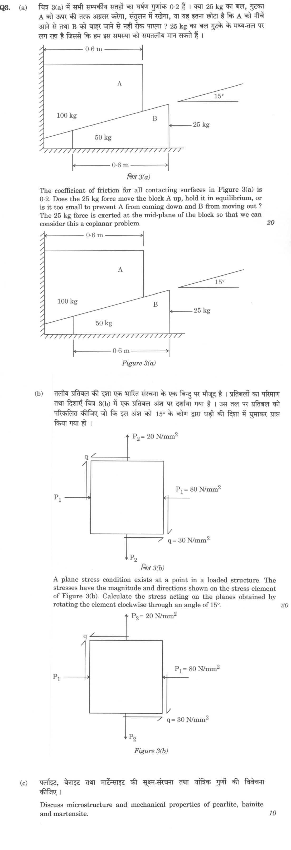
(a) The coefficient of friction for all contacting surfaces in Figure 3(a) is 0·2. Does the 25 kg force move the block A up, hold…
The coefficient of friction for all contacting surfaces in Figure 3(a) is 0·2. Does the 25 kg force move the block A up, hold it in equilibrium, or is it too small to prevent A from coming down and B from moving out ? The 25 kg force is exerted at the mid-plane of the block so that we can consider this a coplanar problem. 20 marks
A plane stress condition exists at a point in a loaded structure. The stresses have the magnitude and directions shown on the stress element of Figure 3(b). Calculate the stress acting on the planes obtained by rotating the element clockwise through an angle of 15°. 20 marks
Discuss microstructure and mechanical properties of pearlite, bainite and martensite. 10 marks
हिंदी में प्रश्न पढ़ें
चित्र 3(a) में सभी संपर्कीय सतहों का घर्षण गुणांक 0·2 है । क्या 25 kg का बल, गुटका A को ऊपर की तरफ अग्रसर करेगा, संतुलन में रखेगा, या यह इतना छोटा है कि A को नीचे आने से तथा B को बाहर जाने से नहीं रोक पाएगा ? 25 kg का बल गुटके के मध्य-तल पर लग रहा है जिससे कि हम इस समस्या को समतलीय मान सकते हैं । (20 अंक)
तलीय प्रतिबल की दशा एक भारित संरचना के एक बिंदु पर मौजूद है । प्रतिबलों का परिमाण तथा दिशाएँ चित्र 3(b) में एक प्रतिबल अंश पर दर्शाया गया है । उस तल पर प्रतिबल को परिकलित कीजिए जो कि इस अंश को 15° के कोण द्वारा घड़ी की दिशा में घुमाकर प्राप्त किया गया हो । (20 अंक)
पर्लाइट, बेनाइट तथा मार्टेंसाइट की सूक्ष्म-संरचना तथा यांत्रिक गुणों की विवेचना कीजिए । (10 अंक)
The figure this question refers to, in words
The question paper is a scan and the diagram did not survive as text. This is the figure as read from the original page — every component, value and label — so the question can be worked from the text below.
(a) A mechanical system consisting of a block A and a wedge B. On the left is a vertical hatched wall, and at the bottom is a horizontal hatched floor. Block A rests against the vertical wall on its left vertical side. Block A has a horizontal top surface of width 0.6 m (measured from the vertical wall to its right vertical face). The bottom surface of block A is inclined at an angle of 15 degrees to the horizontal, sloping upwards from left to right, and extends from the vertical wall to its right vertical face. The mass of block A is labelled as 100 kg. Below block A is wedge B, which rests on the horizontal floor. Wedge B has a horizontal base of length 0.6 m, a vertical left face, a vertical right face, and an inclined top surface at 15 degrees to the horizontal in contact with the inclined bottom surface of block A. The mass of wedge B is labelled as 50 kg. A horizontal force of 25 kg is applied to the right vertical face of wedge B, directed toward the left. The angle of 15 degrees to the horizontal is indicated to the right of the inclined plane.
(b) A rectangular 2D plane stress element labeled Figure 3(b) subjected to normal and shear stresses:
- Normal stresses: Tensile stress P2 = 20 N/mm^2 acting vertically outwards from the top and bottom faces (upward on top face, downward on bottom face). Compressive stress P1 = 80 N/mm^2 acting horizontally inwards onto the left and right faces (pointing right into the left face, pointing left into the right face).
- Shear stresses of magnitude q = 30 N/mm^2: pointing left along the top horizontal edge, pointing right along the bottom horizontal edge, pointing upward along the left vertical edge, and pointing downward along the right vertical edge.
Model answer
Written by UPSC Answer Check against this question's marking rubric, to the expected length. UPSC does not publish answers for Mains — this is one way to score well, not an official key.
(a) Let θ = 15°, μ = 0.2. Work in kg force: W_A = 100 kgf, W_B = 50 kgf, applied force F = 25 kgf leftwards. Let N be the normal reaction between A and B, H the wall reaction on A, and R the floor reaction on B.
For impending motion of A up and B left: interface friction on A acts down the incline, wall friction on A acts down, and floor friction on B acts right. For A:
- x: H = N sinθ + μN cosθ = N(sinθ + μ cosθ)
- y: N cosθ = W_A + μN sinθ + μH Substituting H: N[(1 − μ²)cosθ − 2μ sinθ] = W_A N = 100 / [0.96 × 0.9659 − 0.4 × 0.2588] = 121.4 kgf H = 121.4(0.2588 + 0.2 × 0.9659) = 54.9 kgf For B: R = W_B + N(cosθ − μ sinθ) = 50 + 121.4(0.9659 − 0.2 × 0.2588) = 161.0 kgf Horizontal equilibrium: F_up = H + μR = 54.9 + 0.2 × 161.0 = 87.1 kgf Since 25 kgf < 87.1 kgf, the force cannot move A up.
For impending motion of A down and B right: interface friction on A acts up the incline, wall friction on A acts up, and floor friction on B acts left. For A:
- x: H = N sinθ − μN cosθ = N(sinθ − μ cosθ)
- y: N cosθ + μN sinθ + μH = W_A Substituting H: N[(1 − μ²)cosθ + 2μ sinθ] = W_A N = 100 / [0.96 × 0.9659 + 0.4 × 0.2588] = 97.0 kgf H = 97.0(0.2588 − 0.2 × 0.9659) = 6.37 kgf For B: R = W_B + N(cosθ + μ sinθ) = 50 + 97.0(0.9659 + 0.2 × 0.2588) = 148.7 kgf For impending right motion of B, the required external left force would be: F_right = H − μR = 6.37 − 0.2 × 148.7 = −23.4 kgf The negative sign means no left force is needed to prevent this motion; a rightward force of 23.4 kgf would be required to cause it.
Final answer: the 25 kg force neither moves A up nor is too small. It holds the system in equilibrium.
(b) Take x horizontal right and y vertical up. From the stress element: σ_x = −80 N/mm² (compression), σ_y = +20 N/mm² (tension), τ_xy = −30 N/mm². Clockwise rotation through 15° means θ = −15°, so 2θ = −30°. cos 2θ = 0.8660, sin 2θ = −0.5.
Use the plane-stress transformation equations: σ_x′ = (σ_x + σ_y)/2 + (σ_x − σ_y)/2 cos 2θ + τ_xy sin 2θ = −30 + (−50)(0.8660) + (−30)(−0.5) = −30 − 43.30 + 15 = −58.30 N/mm²
σ_y′ = (σ_x + σ_y)/2 − (σ_x − σ_y)/2 cos 2θ − τ_xy sin 2θ = −30 − (−50)(0.8660) − (−30)(−0.5) = −30 + 43.30 − 15 = −1.70 N/mm²
τ_x′y′ = −(σ_x − σ_y)/2 sin 2θ + τ_xy cos 2θ = −(−50)(−0.5) + (−30)(0.8660) = −25 − 25.98 = −50.98 N/mm²
Thus the rotated element has normal stresses σ_x′ = 58.30 N/mm² compressive, σ_y′ = 1.70 N/mm² compressive, and shear stress magnitude 50.98 N/mm², with sign corresponding to the negative τ_x′y′ direction. Check: σ_x′ + σ_y′ = −60 N/mm², equal to the original invariant σ_x + σ_y.
(c) Pearlite has a lamellar eutectoid microstructure of alternating ferrite and cementite (Fe₃C) layers, formed by diffusion-controlled transformation of austenite at about 550–727°C. Finer interlamellar spacing, obtained at lower transformation temperature, gives higher strength and hardness. It has moderate strength and hardness, good ductility and toughness, and good machinability; typical UTS is about 600–900 MPa and hardness about 15–30 HRC.
Bainite is a non-lamellar aggregate of ferrite and fine carbides formed isothermally at about 250–550°C. Upper bainite (about 400–550°C) has carbides between ferrite laths, while lower bainite (about 250–400°C) has fine carbides inside ferrite laths. Bainite gives a better combination of strength and toughness than pearlite at the same hardness; lower bainite is stronger and tougher than upper bainite. Hardness is typically about 40–55 HRC.
Martensite forms by diffusionless shear transformation of austenite on rapid quenching below the Ms temperature. It is a body-centred tetragonal supersaturated solid solution of carbon in α-iron. Low-carbon martensite is lath-like; high-carbon martensite is plate-like or twinned. It has the highest hardness and strength but low ductility and toughness, is brittle, and develops high residual stresses and cracking tendency. Hardness can reach about 65 HRC for high carbon. Tempering is required to improve toughness.
What "Solve" is asking you to do
Choose the method, then carry it through to a final answer. Identifying what kind of problem this is and why that method applies is the first thing marked; a correct figure arrived at invisibly earns almost nothing.
Structure that answers it
Given data and what is required → method chosen, with the reason it applies → set-up (equation, circuit, free body, trial balance) → working, step by step → answer with units and any condition of validity
Where marks are lost
Doing the middle steps mentally and writing only the result. In mathematics papers, a further loss comes from giving a decimal where the exact value in surds or fractions was wanted, or from skipping the justification a part explicitly asks for.
How this answer will be evaluated
Approach
(a) analyse: intro > causes > effects > stakeholders/linkages > way forward | (b) calculate: given > formula > substitution > result with units > interpretation | (c) discuss: intro > 3-4 dimensions > example > balanced close Full marks: Complete and correct analysis with clear diagrams and reasoning for all parts.
Key points expected
- Free body diagrams for blocks A and B
- Resolve forces into normal and tangential components
- Calculate limiting friction forces at all interfaces
- Compare applied force with required force for motion
- Identify given stresses: σx, σy, and τxy
- Apply stress transformation equations for normal stress
- Apply stress transformation equations for shear stress
- Substitute values with correct sign convention for rotation
Evaluation rubric
Each sub-part is marked on its own, against the marks and word limit printed on the paper.
- (a) Determine if the 25 kg force moves block A up, holds it, or is insufficient. 20 marks
analyse— intro → causes → effects → stakeholders/linkages → way forward
Must cover
- Free body diagrams for blocks A and B
- Resolve forces into normal and tangential components
- Calculate limiting friction forces at all interfaces
- Compare applied force with required force for motion
Loses marks
- Ignoring friction on the vertical wall
- Incorrect angle of inclination for force resolution
Earns more
- Explicit check for impending motion in both directions
- Correct identification of the critical interface
Extra mark
- Clear schematic of the wedge mechanism
- (b) Calculate normal and shear stresses on a plane rotated 15° clockwise. 20 marks
calculate— given → formula → substitution → result with units → interpretation
Must cover
- Identify given stresses: σx, σy, and τxy
- Apply stress transformation equations for normal stress
- Apply stress transformation equations for shear stress
- Substitute values with correct sign convention for rotation
Loses marks
- Using the wrong sign for the rotation angle
- Confusing normal and shear stress formulas
Earns more
- Correct handling of the 15° clockwise rotation angle
- Final results with units (N/mm²)
Extra mark
- Mention of Mohr's circle as a verification method
- (c) Discuss microstructure and mechanical properties of pearlite, bainite, and martensite. 10 marks
discuss— intro → 3-4 dimensions → example → balanced close
Must cover
- Describe the microstructure of each of the three phases
- State the mechanical properties (hardness, strength, ductility) of each
- Link microstructure to the resulting mechanical properties
- Compare the three phases in terms of their properties
Loses marks
- Confusing the microstructure of pearlite and bainite
- Failing to link structure to properties
Earns more
- Mention of the formation conditions (cooling rate) for each
- Reference to the iron-carbon phase diagram
Extra mark
- Mention of specific applications for each microstructure
Practice this exact question
Write your answer and it is marked point by point against the model answer above — what you covered, what you missed, what you got wrong.
Evaluate my answer →More from Mechanical Engineering 2023 Paper I
- Q1 (a) A heavy carriage wheel of weight W, and radius r is to be dragged over an obstacle of…
- Q2 (a) In Figure 2(a), AB is a rigid bar, CE is a steel rod of 20 mm diameter and DF is a co…
- Q3 (a) The coefficient of friction for all contacting surfaces in Figure 3(a) is 0·2. Does t…
- Q4 (a) Two involute gears in mesh have pressure angle of 20° and module of 6 mm. The number…
- Q5 (a) In an electrochemical machining process of an iron surface using sodium chloride solu…
- Q6 (a) Following data were observed while machining two different work materials X and Y usi…