Paper II — Q6
(a) A synchronous machine is connected to an infinite bus through a transformer and a double circuit line as shown in figure. The…
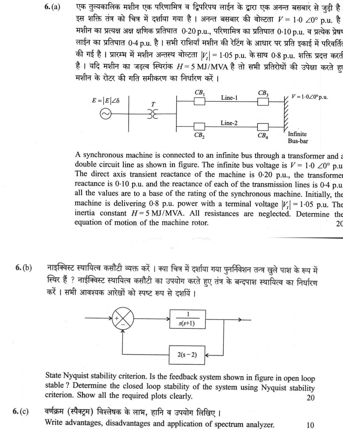
A synchronous machine is connected to an infinite bus through a transformer and a double circuit line as shown in figure. The infinite bus voltage is V = 1·0 ∠0° p.u. The direct axis transient reactance of the machine is 0·20 p.u., the transformer reactance is 0·10 p.u. and the reactance of each of the transmission lines is 0·4 p.u. all the values are to a base of the rating of the synchronous machine. Initially, the machine is delivering 0·8 p.u. power with a terminal voltage |Vₜ| = 1·05 p.u. The inertia constant H = 5 MJ/MVA. All resistances are neglected. Determine the equation of motion of the machine rotor. 20 marks
State Nyquist stability criterion. Is the feedback system shown in figure in open loop stable ? Determine the closed loop stability of the system using Nyquist stability criterion. Show all the required plots clearly. 20 marks
Write advantages, disadvantages and application of spectrum analyzer. 10 marks
हिंदी में प्रश्न पढ़ें
एक तुल्यकालिक मशीन एक परिणामित्र व द्विपरिपथ लाइन के द्वारा एक अनंत बसबार से जुड़ी है । इस शक्ति तंत्र को चित्र में दर्शाया गया है । अनंत बसबार की बोल्टता V = 1·0 ∠0° p.u. है । मशीन का प्रत्यक्ष अक्ष क्षणिक प्रतिघात 0·20 p.u., परिणामित्र का प्रतिघात 0·10 p.u. व प्रत्येक प्रेषण लाइन का प्रतिघात 0·4 p.u. है । सभी राशियाँ मशीन की रेटिंग के आधार पर प्रति इकाई में परिवर्तित की गई है । प्रारंभ में मशीन अंतर्य बोल्टता |Vₜ| = 1·05 p.u. के साथ 0·8 p.u. शक्ति प्रदान करती है । यदि मशीन का जड़त्व स्थिरांक H = 5 MJ/MVA है तो सभी प्रतिरोधों की उपेक्षा करते हुए मशीन के रोटर की गति समीकरण का निर्धारण करें । 20
नाइक्विस्ट स्थायित्व कसौटी व्यक्त करें । क्या चित्र में दर्शाया गया पुनर्निवेश तंत्र खुले पाश के रूप में स्थिर है ? नाइक्विस्ट स्थायित्व कसौटी का उपयोग करते हुए तंत्र के बंदपाश स्थायित्व का निर्धारण करें । सभी आवश्यक आरेखों को स्पष्ट रूप से दर्शायें । 20
वर्णक्रम (स्पेक्ट्रम) विश्लेषक के लाभ, हानि व उपयोग लिखिए । 10
The figure this question refers to, in words
The question paper is a scan and the diagram did not survive as text. This is the figure as read from the original page — every component, value and label — so the question can be worked from the text below.
(a) A single-line power system diagram showing a synchronous generator connected to an infinite busbar through a transformer and a double-circuit transmission line. On the left, the generator is depicted as an AC source symbol with internal voltage labelled E = |E|∠δ. Its terminal connects to a vertical bus, followed by a transformer labelled T. After transformer T, a vertical bus splits into two parallel branches: the upper branch has a circuit breaker labelled CB1, followed by a transmission line labelled 'Line-1', and another circuit breaker labelled CB3; the lower branch has a circuit breaker labelled CB2, followed by a transmission line labelled 'Line-2', and another circuit breaker labelled CB4. Both parallel lines rejoin at a hatched vertical bus on the far right labelled 'Infinite Bus-bar' with voltage labelled V = 1.0∠0° p.u.
(b) A block diagram of a closed-loop feedback control system. An input enters a summing point at a positive (+) terminal. The error signal from the summing point enters a forward path block with transfer function 1 / [s(s + 1)]. The output of this block is the system output. A feedback loop taps off this output and feeds into a feedback block with transfer function 2(s - 2). The output of the feedback block is connected to the negative (-) terminal of the summing point.
Model answer
Written by UPSC Answer Check against this question's marking rubric, to the expected length. UPSC does not publish answers for Mains — this is one way to score well, not an official key.
(a) Using the classical swing-equation model, neglect resistance and take both lines in service. The line equivalent reactance is ∦: XL = 0.4 ∥ 0.4 = (0.4×0.4)/(0.4+0.4) = 0.20 p.u. Total reactance from transient internal voltage E′ to infinite bus: X = Xd′ + Xt + XL = 0.20 + 0.10 + 0.20 = 0.50 p.u. Transformer-plus-line reactance from terminal to infinite bus: Xtl = Xt + XL = 0.10 + 0.20 = 0.30 p.u.
Let terminal voltage be Vt = |Vt|∠θ = 1.05∠θ p.u. Power delivered to infinite bus is P = (|Vt||V|/Xtl) sin θ. 0.8 = (1.05×1.0/0.30) sin θ sin θ = (0.8×0.30)/1.05 = 0.228571. θ = 13.21°, cos θ = 0.973527. Thus Vt = 1.05(0.973527 + j0.228571) = 1.02220 + j0.24000 p.u.
Current from terminal to infinite bus: I = (Vt − V)/(jXtl) = (0.02220 + j0.24000)/(j0.30) I = 0.8000 − j0.07401 p.u.
Now E′ behind Xd′: E′ = Vt + jXd′I = (1.02220 + j0.24000) + j0.20(0.8000 − j0.07401) = 1.03701 + j0.40000 p.u. |E′| = √(1.03701² + 0.40000²) = 1.1115 p.u. δ0 = tan⁻¹(0.40000/1.03701) = 21.09° = 0.368 rad.
Power-angle equation after the initial condition is Pe = (|E′||V|/X) sin δ = (1.1115×1.0/0.50) sin δ = 2.223 sin δ p.u.
Mechanical input is initially Pm = 0.8 p.u. Using swing equation (2H/ωs) d²δ/dt² = Pm − Pe. H = 5 MJ/MVA, f = 50 Hz, ωs = 2π×50 = 314.16 rad/s. M = 2H/ωs = 10/314.16 = 0.03183 s²/rad.
Therefore 0.03183 d²δ/dt² = 0.8 − 2.223 sin δ or d²δ/dt² = 25.13 − 69.83 sin δ rad/s², with initial conditions δ(0) = 0.368 rad, dδ/dt(0) = 0. Valid for constant Pm, constant E′, no damping, and both line sections in service.
(b) Nyquist stability criterion: For open-loop transfer function L(s) = G(s)H(s), the number of closed-loop poles in the right-half plane is Z = N + P, where P is the number of open-loop poles in the right-half plane and N is the number of clockwise encirclements of the point −1 + j0 by the Nyquist plot of L(s).
Here L(s) = G(s)H(s) = [1/{s(s+1)}] × 2(s−2) = 2(s−2)/[s(s+1)].
Open-loop poles are s = 0 and s = −1. There are no right-half-plane poles, so P = 0 for Nyquist counting. However, because of the pole at s = 0, the open-loop system is not asymptotically or BIBO stable; it is only marginally stable.
Now L(jω) = 2(jω−2)/[jω(jω+1)] = 6/(ω²+1) + j 2(2−ω²)/[ω(ω²+1)].
For ω > 0:
- as ω → 0⁺, L → 6 + j∞,
- at ω = √2, L = 2 + j0,
- as ω → ∞, L → 0 − j0. The negative-frequency plot is its mirror image. The pole at the origin is indented into the right-half plane, producing a large arc centred at 6 + j0, passing through −∞ on the real axis. Hence the complete Nyquist plot encircles the critical point −1 + j0 once clockwise.
Now closed-loop characteristic equation: 1 + L(s) = 0 1 + 2(s−2)/[s(s+1)] = 0 s(s+1) + 2(s−2) = 0 s² + 3s − 4 = 0 (s − 1)(s + 4) = 0. The closed-loop poles are s = 1 and s = −4. Since one pole lies in the right-half plane, the closed-loop system is unstable.
Using Nyquist: P = 0, N = 1 clockwise encirclement, so Z = N + P = 1. Thus there is one closed-loop right-half-plane pole. The closed-loop system is unstable.
(c) Advantages of a spectrum analyzer:
- Displays amplitude versus frequency, so harmonics, sidebands, noise and spurious components are directly visible.
- Useful over a very wide frequency range, from audio to microwave.
- High dynamic range and calibrated amplitude/frequency readout.
- FFT types give fast real-time spectrum analysis for transient and modulated signals.
Disadvantages:
- Cost and complexity are high, especially for microwave and high-resolution models.
- Real-time bandwidth may be limited.
- Resolution bandwidth, sweep time and dynamic range involve trade-offs.
- Strong signals can overload the input, causing spurious responses.
Applications:
- RF/microwave transmitter and receiver testing.
- EMI/EMC measurements and spectrum monitoring.
- Harmonic distortion, intermodulation and phase-noise measurements.
- Audio, vibration and communication-signal analysis.
What "Solve" is asking you to do
Choose the method, then carry it through to a final answer. Identifying what kind of problem this is and why that method applies is the first thing marked; a correct figure arrived at invisibly earns almost nothing.
Structure that answers it
Given data and what is required → method chosen, with the reason it applies → set-up (equation, circuit, free body, trial balance) → working, step by step → answer with units and any condition of validity
Where marks are lost
Doing the middle steps mentally and writing only the result. In mathematics papers, a further loss comes from giving a decimal where the exact value in surds or fractions was wanted, or from skipping the justification a part explicitly asks for.
How this answer will be evaluated
Approach
Framework: Electrical Engineering, Paper 2. (a) calculate: given > formula > substitution > result with units > interpretation | (b) examine: intro > how/why with reasoning > evidence > conclusion | (c) write short notes: define > 3-4 key features > one example > one-line significance Full marks: Complete derivations with correct units, clear plots, and all required parameters identified.
Key points expected
- Calculate total reactance (Xt + Xd' + Xline/2)
- Determine internal EMF (E) from power flow
- Compute inertia constant M in p.u. seconds
- State final swing equation d²δ/dt² = Pm - Pe
- State Nyquist stability criterion clearly
- Identify open-loop poles for stability check
- Sketch Nyquist plot of G(s)H(s)
- Count encirclements of -1 point for conclusion
Evaluation rubric
Each sub-part is marked on its own, against the marks and word limit printed on the paper.
- (a) Derive the swing equation for the rotor using per-unit system parameters. 20 marks
calculate— given → formula → substitution → result with units → interpretation
Must cover
- Calculate total reactance (Xt + Xd' + Xline/2)
- Determine internal EMF (E) from power flow
- Compute inertia constant M in p.u. seconds
- State final swing equation d²δ/dt² = Pm - Pe
Loses marks
- Ignoring parallel line reactance
- Using steady-state reactance instead of transient
- Missing units in final equation
Earns more
- Draw equivalent circuit with reactances
- Show phasor diagram for voltage/current
- Calculate power angle δ explicitly
Extra mark
- Verify power balance at infinite bus
- (b) Apply Nyquist criterion to determine open and closed loop stability. 20 marks
examine— intro → how/why with reasoning → evidence → conclusion
Must cover
- State Nyquist stability criterion clearly
- Identify open-loop poles for stability check
- Sketch Nyquist plot of G(s)H(s)
- Count encirclements of -1 point for conclusion
Loses marks
- Incorrect open-loop transfer function
- Missing encirclement count
- Confusing open and closed loop stability
Earns more
- Calculate gain and phase margins
- Show Bode plot for cross-check
- Label critical points on Nyquist plot
Extra mark
- Discuss effect of time delay on stability
- (c) List pros, cons, and uses of a spectrum analyzer. 10 marks
write short notes— define → 3-4 key features → one example → one-line significance
Must cover
- Define spectrum analyzer function
- List at least 3 advantages
- List at least 3 disadvantages
- Give 2-3 specific applications
Loses marks
- Vague or generic points
- Missing applications section
- Confusing with signal generator
Earns more
- Mention dynamic range or resolution bandwidth
- Compare with oscilloscope
- Cite specific industry use (RF, audio)
Extra mark
- Mention specific model or standard
Practice this exact question
Write your answer and it is marked point by point against the model answer above — what you covered, what you missed, what you got wrong.
Evaluate my answer →More from Electrical Engineering 2021 Paper II
- Q3 3.(a) A solidly earthed 400 KV, 3 phase busbar system is connected with two incoming and…
- Q4 4.(a)(i) The configuration of a 400 KV 3 phase line is shown in figure. The radius of eac…
- Q5 (a) Explain the ratio error and phase angle error of current transformer. 10 marks (b) Th…
- Q6 (a) A synchronous machine is connected to an infinite bus through a transformer and a dou…
- Q7 (a) Discuss the percentage differential Relay with harmonic restraint with the help of di…
- Q8 (a)(i) Prove that the minimum distance of any linear (n, k) block code satisfies dmin ≤ 1…