Paper II — Q5
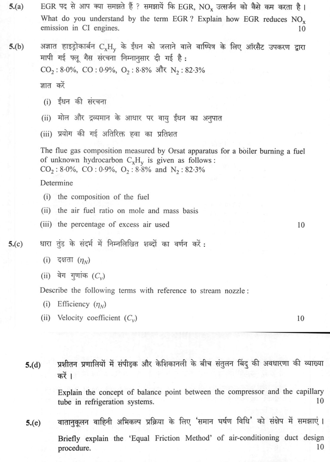
(a) What do you understand by the term EGR? Explain how EGR reduces NOₓ emission in CI engines. (10 marks) (b) The flue gas…
What do you understand by the term EGR? Explain how EGR reduces NOₓ emission in CI engines. 10 marks
The flue gas composition measured by Orsat apparatus for a boiler burning a fuel of unknown hydrocarbon CₓHᵧ is given as follows: CO₂: 8·0%, CO: 0·9%, O₂: 8·8% and N₂: 82·3%. Determine (i) the composition of the fuel (ii) the air fuel ratio on mole and mass basis (iii) the percentage of excess air used. 10 marks
Describe the following terms with reference to stream nozzle: (i) Efficiency (ηₙ) (ii) Velocity coefficient (Cᵥ). 10 marks
Explain the concept of balance point between the compressor and the capillary tube in refrigeration systems. 10 marks
Briefly explain the 'Equal Friction Method' of air-conditioning duct design procedure. 10 marks
हिंदी में प्रश्न पढ़ें
EGR पद से आप क्या समझते हैं? समझायें कि EGR, NOₓ उत्सर्जन को कैसे कम करता है। (10 अंक)
अज्ञात हाइड्रोकार्बन CₓHᵧ के ईंधन को जलाने वाले वाष्पित्र के लिए ऑर्सेट उपकरण द्वारा मापी गई फ्लू गैस संरचना निम्नानुसार दी गई है: CO₂: 8·0%, CO: 0·9%, O₂: 8·8% और N₂: 82·3%। ज्ञात करें (i) ईंधन की संरचना (ii) मोल और द्रव्यमान के आधार पर वायु ईंधन का अनुपात (iii) प्रयोग की गई अतिरिक्त हवा का प्रतिशत। (10 अंक)
धारा तुंड के संदर्भ में निम्नलिखित शब्दों का वर्णन करें: (i) दक्षता (ηₙ) (ii) वेग गुणांक (Cᵥ)। (10 अंक)
प्रशीतन प्रणालियों में संपीड़क और केशिकानली के बीच संतुलन बिंदु की अवधारणा की व्याख्या करें। (10 अंक)
वातानुकूलन वाहिनी अभिकल्प प्रक्रिया के लिए 'समान घर्षण विधि' को संक्षेप में समझाएं। (10 अंक)
Model answer
Written by UPSC Answer Check against this question's marking rubric, to the expected length. UPSC does not publish answers for Mains — this is one way to score well, not an official key.
(a) EGR, or Exhaust Gas Recirculation, is the deliberate recirculation of a small fraction of cooled exhaust gas back into the intake charge of a spark or compression ignition engine. In CI engines the main purpose is NOx control. NOx is formed thermally in the Zeldovich mechanism when local temperatures exceed about 1800 K and oxygen is available. EGR reduces NOx by two linked effects. First, the inert CO2 and N2 in the recirculated gas increase heat capacity and lower peak combustion temperature, often below the 1800 K threshold, so the rate of NO formation falls sharply. Second, dilution lowers the local oxygen concentration and slows the chain reactions that produce NO and NO2. In practice, cooled EGR also reduces charge temperature, improves knock resistance in SI engines, and in CI engines can reduce soot while requiring careful control to avoid smoke and fuel consumption penalties. Under BS VI, light-duty vehicles face an 80 mg/km NOx limit, while heavy-duty engines are regulated by engine dynamometer limits in g/kWh; EGR is therefore a core engine-side strategy in Indian emission control.
(b) Taking 100 kmol of dry flue gas as basis, the Orsat analysis gives CO2 = 8.0, CO = 0.9, O2 = 8.8 and N2 = 82.3 kmol. Since air is taken as 21 percent O2 and 79 percent N2 by volume, the oxygen supplied with the air is 82.3 × 21/79 = 21.88 kmol O2. Carbon balance gives carbon in fuel = 8.0 + 0.9 = 8.9 kmol C. Oxygen balance, written in O2-molecule form, is O2 supplied = CO2 + 0.5 CO + 0.5 H2O + O2 in flue gas. Hence H2O = 2(21.88 - 8.0 - 0.5×0.9 - 8.8) = 9.25 kmol. Hydrogen in fuel is therefore 2 × 9.25 = 18.51 kmol H. On this 100 kmol dry-gas basis the fuel equivalent is C8.9H18.51; normalised to one carbon atom it is CH2.08. The theoretical oxygen required for C8.9H18.51 is 8.9 + 18.51/4 = 13.53 kmol O2. The actual oxygen supplied is 21.88 kmol, so the percentage excess air is (21.88 - 13.53)/13.53 × 100 = 61.7 percent. The total air supplied is 21.88 + 82.3 = 104.18 kmol. If the fuel is written as C8.9H18.51, the molar air-fuel ratio is 104.18 kmol air per kmol fuel; if normalised to CH2.08, the molar air-fuel ratio is 104.18/8.9 = 11.71 kmol air per kmol fuel. The molar mass of C8.9H18.51 is 8.9×12 + 18.51×1 = 125.31 kg/kmol. The mass of air is 104.18 × 28.97 = 3018 kg, and the mass of fuel is 125.31 kg, giving a mass air-fuel ratio of about 24.1 kg air per kg fuel. The same mass ratio is obtained from the CH2.08 basis, confirming the result.
(c) For a steam nozzle, nozzle efficiency is the ratio of the actual kinetic energy obtained at the exit to the kinetic energy that would be obtained in an isentropic expansion from the same inlet state to the same exit pressure. If inlet velocity is small, ηn = (h1 - h2)/(h1 - h2s) = V actual squared / V isentropic squared, where h1 is inlet enthalpy, h2 is actual exit enthalpy, h2s is isentropic exit enthalpy, and V is exit velocity. It accounts for friction, turbulence and other irreversibilities inside the nozzle. The velocity coefficient is the ratio of actual exit velocity to the ideal isentropic exit velocity, Cv = V actual / V isentropic. Since velocities are proportional to the square root of kinetic energy, Cv = square root of ηn. For well-designed nozzles Cv is usually 0.95 to 0.99; lower values indicate greater frictional loss and lower available jet velocity.
(d) In a capillary-tube refrigeration system, the balance point is the operating condition at which the mass flow of refrigerant through the capillary tube equals the mass flow handled by the compressor. On a pressure-enthalpy diagram, for a chosen condensing pressure, the capillary tube flow increases as evaporating pressure falls because the pressure drop increases, while the compressor mass flow generally falls because the pressure ratio rises. Their intersection fixes the stable operation zone, the stable evaporating pressure, condensing pressure, refrigerant mass flow and degree of subcooling. At this point, the liquid supplied to the evaporator matches the vapor removed by the compressor, so refrigerant does not accumulate in the evaporator or condenser. If the evaporating pressure deviates, the mismatch between capillary flow and compressor flow drives the system back toward the intersection; this is why a properly selected capillary tube gives self-regulating operation. In tropical Indian conditions, high ambient temperature raises condensing pressure, shifts the balance point, and can reduce capacity if the capillary tube is too long or too small; hence balance-point selection is important for stable cooling and correct subcooling.
(e) The Equal Friction Method is a duct-sizing procedure in which the frictional pressure drop per unit length of duct is kept constant for all main ducts and branches. The designer first estimates the air volume flow in each duct from room loads, then selects a reasonable velocity, usually 2 to 4 m/s for mains and lower for branches, and reads the corresponding friction loss from a duct friction chart or Moody diagram. A typical design friction rate is 0.5 to 1.0 Pa/m for commercial air-conditioning ducts. The same friction rate is then applied to each branch; the duct diameter is adjusted until the calculated friction loss per metre matches the chosen value. The process is iterative: if the chosen velocity gives a friction rate outside the selected range, the diameter is changed and the velocity recalculated. Fitting losses, grille losses and coil losses are added separately, and the total external static pressure is used to select the fan. If the total pressure is too high, the friction rate or velocities are revised. For a simple layout, a main duct serving three rooms might be sized at 0.8 Pa/m; each branch is then sized so that its straight-run friction loss is also 0.8 Pa/m, after which branch fitting losses are checked. The method is simple, economical and widely used in Indian commercial buildings with relatively uniform loading, such as offices, hospitals and retail spaces, where tropical climate design requires reliable air distribution and low fan energy.
What "Explain" is asking you to do
Make the working of something clear — what sets it off, what follows from what, and what it produces. Explain is the Commission's mechanism word: it dominates the technical papers and the “explain why” stems, where the marks sit in the causal chain and not in the label.
Structure that answers it
State what it is → the initiating condition → the chain of cause, step by step → an instance where it plays out → what the chain produces
Where marks are lost
Describing what something looks like instead of why it works that way. Naming the stages without linking them reads as description too.
How this answer will be evaluated
Approach
(a) explain: definition/context > points in order > small example > short close | (b) calculate: given > formula > substitution > result with units > interpretation | (c) describe: define > structure or process in order > labelled diagram > significance | (d) explain: definition/context > points in order > small example > short close | (e) explain: definition/context > points in order > small example > short close Full marks: All parts answered with correct method, clear diagrams, and physical interpretation.
Key points expected
- Define EGR as recirculation of exhaust gas
- Explain reduction of peak combustion temperature
- Link temperature drop to reduced thermal NOx formation
- Mention dilution effect on oxygen concentration
- Normalize flue gas composition to 100 moles
- Determine C and H ratio from CO2 and CO
- Calculate theoretical air requirement
- Compute actual air from N2 balance
Evaluation rubric
Each sub-part is marked on its own, against the marks and word limit printed on the paper.
- (a) Define EGR and explain the mechanism of NOx reduction in CI engines. 10 marks
explain— definition/context → points in order → small example → short close
Must cover
- Define EGR as recirculation of exhaust gas
- Explain reduction of peak combustion temperature
- Link temperature drop to reduced thermal NOx formation
- Mention dilution effect on oxygen concentration
Loses marks
- Confusing EGR with intercooling
- Ignoring the temperature mechanism
Earns more
- Mention effect on combustion duration
- Reference to Zeldovich mechanism
Extra mark
- Schematic of EGR loop in engine
- (b) Determine fuel composition, A/F ratio (mole & mass), and excess air %. 10 marks
calculate— given → formula → substitution → result with units → interpretation
Must cover
- Normalize flue gas composition to 100 moles
- Determine C and H ratio from CO2 and CO
- Calculate theoretical air requirement
- Compute actual air from N2 balance
Loses marks
- Ignoring CO in carbon balance
- Using mass basis for mole calculation
Earns more
- Show step-by-step stoichiometric calculation
- State assumptions (e.g., dry basis)
Extra mark
- Tabulated results for clarity
- (c) Define nozzle efficiency and velocity coefficient with reference to steam nozzles. 10 marks
describe— define → structure or process in order → labelled diagram → significance
Must cover
- Define efficiency as ratio of actual to ideal KE
- Define velocity coefficient as ratio of actual to ideal velocity
- Provide mathematical expressions for both
- Explain physical significance of losses
Loses marks
- Confusing nozzle efficiency with isentropic efficiency
- Missing the square root relationship between Cv and eta
Earns more
- Mention factors affecting efficiency (friction, shape)
Extra mark
- T-s diagram showing ideal vs actual expansion
- (d) Explain the balance point between compressor and capillary tube. 10 marks
explain— definition/context → points in order → small example → short close
Must cover
- Define balance point as equilibrium of mass flow
- Explain compressor capacity vs capillary resistance
- Describe effect of high/low balance point on performance
- Mention impact on suction and discharge pressures
Loses marks
- Treating it as a fixed pressure point
- Ignoring the dynamic nature of the balance
Earns more
- Graph of compressor capacity vs capillary flow
Extra mark
- Example of mismatched components
- (e) Explain the 'Equal Friction Method' for air-conditioning duct design. 10 marks
explain— definition/context → points in order → small example → short close
Must cover
- Define method as constant friction loss per unit length
- Explain selection of friction rate (e.g., 0.1 in w.g./100 ft)
- Describe procedure for sizing main and branch ducts
- Mention balancing of static pressure
Loses marks
- Confusing with constant velocity method
- Ignoring the role of static regain
Earns more
- Comparison with other methods (e.g., constant velocity)
Extra mark
- Sample calculation of duct diameter
Practice this exact question
Write your answer and it is marked point by point against the model answer above — what you covered, what you missed, what you got wrong.
Evaluate my answer →More from Mechanical Engineering 2021 Paper II
- Q2 (a)(i) 3 kg of air is compressed in a reversible steady flow polytropic process from 100…
- Q3 (a)(i) Show that the effective conductance, (A_1F̄₁₂) for two black, parallel plates of e…
- Q4 (a) Two walls A and B are maintained at temperatures T_A and T_B, respectively. One end o…
- Q5 (a) What do you understand by the term EGR? Explain how EGR reduces NOₓ emission in CI en…
- Q6 (a) (i) How does the mixture combustion in the combustion chamber of a C.I. engine differ…
- Q7 (a) (i) A single stage impulse steam turbine rotor has a diameter of 1·2 m and runs at 30…
- Q8 (a) An ammonia vapour compression refrigeration system works between temperature limits o…