Paper II — Q3
(a) (i) How do the specific work output and efficiency vary with pressure ratio in a gas turbine? (ii) Prove that the efficiency…
How do the specific work output and efficiency vary with pressure ratio in a gas turbine?
Prove that the efficiency of a gas turbine corresponding to the maximum work done in a Brayton cycle is given by the relation
η_w max = 1 - 1/(√t)
where t is the ratio of the maximum and minimum temperatures.
20 marks
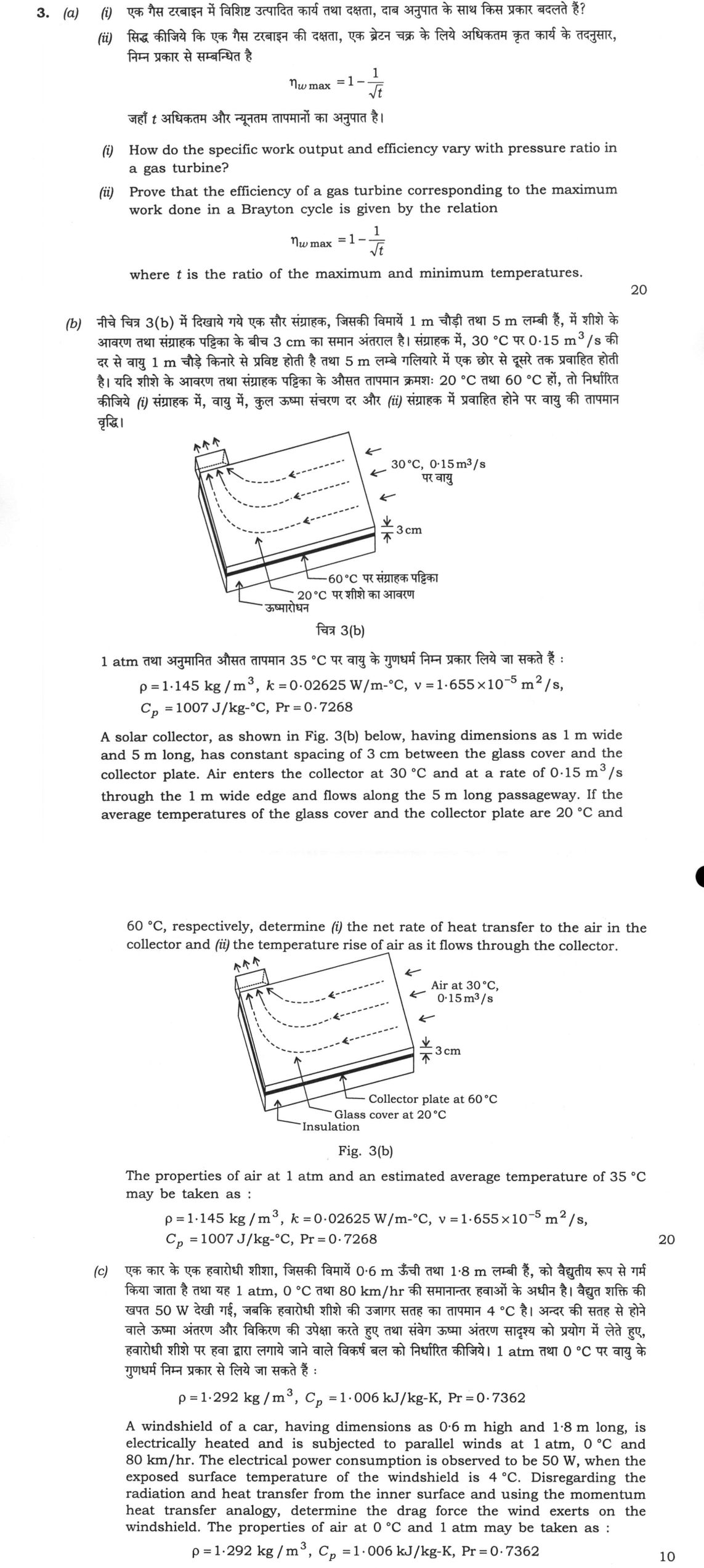
A solar collector, as shown in Fig. 3(b) below, having dimensions as 1 m wide and 5 m long, has constant spacing of 3 cm between the glass cover and the collector plate. Air enters the collector at 30 °C and at a rate of 0·15 m³/s through the 1 m wide edge and flows along the 5 m long passageway. If the average temperatures of the glass cover and the collector plate are 20 °C and 60 °C, respectively, determine (i) the net rate of heat transfer to the air in the collector and (ii) the temperature rise of air as it flows through the collector.
Fig. 3(b)
The properties of air at 1 atm and an estimated average temperature of 35 °C may be taken as :
ρ = 1·145 kg/m³, k = 0·02625 W/m-°C, ν = 1·655×10⁻⁵ m²/s, Cₚ = 1007 J/kg-°C, Pr = 0·7268
20 marks
A windshield of a car, having dimensions as 0·6 m high and 1·8 m long, is electrically heated and is subjected to parallel winds at 1 atm, 0 °C and 80 km/hr. The electrical power consumption is observed to be 50 W, when the exposed surface temperature of the windshield is 4 °C. Disregarding the radiation and heat transfer from the inner surface and using the momentum heat transfer analogy, determine the drag force the wind exerts on the windshield. The properties of air at 0 °C and 1 atm may be taken as :
ρ = 1·292 kg/m³, Cₚ = 1·006 kJ/kg-K, Pr = 0·7362
10 marks
हिंदी में प्रश्न पढ़ें
एक गैस टरबाइन में विशिष्ट उत्पादित कार्य तथा दक्षता, दाब अनुपात के साथ किस प्रकार बदलते हैं?
सिद्ध कीजिए कि एक गैस टरबाइन की दक्षता, एक ब्रेटन चक्र के लिये अधिकतम कृत कार्य के तदनुसार, निम्न प्रकार से सम्बन्धित है
η_w max = 1 - 1/(√t)
जहाँ t अधिकतम और न्यूनतम तापमानों का अनुपात है।
(20 अंक)
नीचे चित्र 3(b) में दिखाये गये एक सौर संग्राहक, जिसकी विमायें 1 m चौड़ी तथा 5 m लम्बी हैं, में शीशे के आवरण तथा संग्राहक पट्टिका के बीच 3 cm का समान अन्तराल है। संग्राहक में, 30 °C पर 0·15 m³/s की दर से वायु 1 m चौड़े किनारे से प्रविष्ट होती है तथा 5 m लम्बे गलियारे में एक छोर से दूसरे तक प्रवाहित होती है। यदि शीशों के आवरण तथा संग्राहक पट्टिका के औसत तापमान क्रमशः: 20 °C तथा 60 °C हों, तो निर्धारित कीजिये (i) संग्राहक में, वायु में, कुल ऊष्मा संचरण दर और (ii) संग्राहक में प्रवाहित होने पर वायु की तापमान वृद्धि।
1 atm तथा अनुमानित औसत तापमान 35 °C पर वायु के गुणधर्म निम्न प्रकार लिये जा सकते हैं :
ρ = 1·145 kg/m³, k = 0·02625 W/m-°C, ν = 1·655×10⁻⁵ m²/s, Cₚ = 1007 J/kg-°C, Pr = 0·7268
(20 अंक)
एक कार के एक हवारोधी शीशा, जिसकी विमायें 0·6 m ऊँची तथा 1·8 m लम्बी हैं, को वैद्युतीय रूप से गर्म किया जाता है तथा यह 1 atm, 0 °C तथा 80 km/hr की समानान्तर हवाओं के अधीन है। वैद्युत शक्ति की खपत 50 W देखी गई, जबकि हवारोधी शीशे की उजागर सतह का तापमान 4 °C है। अन्दर की सतह से होने वाले ऊष्मा अन्तरण और विकिरण की उपेक्षा करते हुए तथा संवेग ऊष्मा अन्तरण सादृश्य को प्रयोग में लेते हुए, हवारोधी शीशे पर हवा द्वारा लगाये जाने वाले विकर्ष बल को निर्धारित कीजिये। 1 atm तथा 0 °C पर वायु के गुणधर्म निम्न प्रकार से लिये जा सकते हैं :
ρ = 1·292 kg/m³, Cₚ = 1·006 kJ/kg-K, Pr = 0·7362
(10 अंक)
The figure this question refers to, in words
The question paper is a scan and the diagram did not survive as text. This is the figure as read from the original page — every component, value and label — so the question can be worked from the text below.
(b) A schematic 3D diagram of a flat solar collector duct/passageway labeled 'चित्र 3(b)'. It depicts a rectangular channel with two parallel plates separated by a uniform spacing of 3 cm (indicated by vertical dimension arrows labeled '3 cm'). The upper surface is labeled as the glass cover at 20 °C ('20 °C पर शीशे का आवरण'). Below the channel is the collector plate maintained at 60 °C ('60 °C पर संग्राहक पट्टिका'), underneath which is an insulation layer ('ऊष्मारोधन'). Air enters the channel from one edge, indicated by three parallel inlet arrows labeled '30 °C, 0·15 m^3/s पर वायु' (air at 30 °C, 0.15 m^3/s). Dashed arrows illustrate the flow path along the interior length of the passage toward the opposite end, where three outlet arrows indicate the flow exit.
(b) Fig. 3(b) shows a cross-sectional perspective view of a flat-plate solar air collector duct. The top surface is labelled 'Glass cover at 20 °C'. The bottom surface is labelled 'Collector plate at 60 °C', beneath which is a layer with diagonal hatch marks labelled 'Insulation'. The vertical spacing (channel height) between the glass cover and the collector plate is 3 cm. Air enters the duct from the right end, indicated by horizontal arrows pointing left, with the label 'Air at 30 °C, 0.15 m^3/s'. Dashed horizontal arrows show the airflow path from right to left through the channel. At the left exit of the duct, three arrows point outward and slightly upward, indicating the airflow outlet.
Model answer
Written by UPSC Answer Check against this question's marking rubric, to the expected length. UPSC does not publish answers for Mains — this is one way to score well, not an official key.
(a)(i) For an ideal Brayton gas-turbine cycle with fixed minimum temperature T₁ and maximum temperature T₃, let pressure ratio r_p = p₂/p₁, a = (γ−1)/γ, and x = r_p^a = T₂/T₁. Then
- Compressor work: w_C = Cp T₁(x−1)
- Turbine work: w_T = Cp T₃(1−1/x)
- Net specific work: w_net = Cp[T₃(1−1/x) − T₁(x−1)]
As r_p increases from 1, w_net rises from zero, reaches a maximum at x = √(T₃/T₁), then decreases; beyond a high pressure ratio the compressor work becomes dominant and net work may become zero or negative. The ideal thermal efficiency is
η = 1 − T₁/T₂ = 1 − 1/x = 1 − 1/r_p^a
so η increases monotonically with pressure ratio and approaches 1. Thus, higher r_p always improves ideal efficiency, but specific work is maximum only at an optimum pressure ratio depending on T₃/T₁.
(a)(ii) For maximum work, differentiate w_net/Cp = T₃ + T₁ − T₁x − T₃/x with respect to x:
d/dx [T₃ + T₁ − T₁x − T₃/x] = −T₁ + T₃/x² = 0
Hence T₃/T₁ = x² = t, so x = √t. At this condition,
η_wmax = 1 − 1/x = 1 − 1/√t
Therefore, η_wmax = 1 − 1/√t, valid for an ideal Brayton cycle with constant Cp, no pressure losses, and no regeneration.
(b)(i) From Fig. 3(b), width W = 1 m, length L = 5 m, spacing H = 0.03 m. Cross-sectional area:
A_c = WH = 1 × 0.03 = 0.03 m²
Velocity:
u = V_dot/A_c = 0.15/0.03 = 5 m/s
Hydraulic diameter:
D_h = 4A_c/P = 4(0.03)/[2(1+0.03)] = 0.05825 m
Reynolds number:
Re = uD_h/ν = 5 × 0.05825 / (1.655×10⁻⁵) = 1.76×10⁴
Flow is turbulent. Using Dittus–Boelter for heating, n = 0.4:
Nu = 0.023 Re^0.8 Pr^0.4 Nu = 0.023 × (1.76×10⁴)^0.8 × 0.7268^0.4 = 50.43
Heat-transfer coefficient:
h = Nu k/D_h = 50.43 × 0.02625 / 0.05825 = 22.7 W/m²°C
Each heat-transfer surface area:
A_s = WL = 1 × 5 = 5 m²
Using estimated air average temperature 35 °C, net heat to air is heat gained from collector plate minus heat lost to glass cover:
q_net = hA_s[(60−35) − (35−20)] q_net = 22.7 × 5 × 10 = 1135 W
Answer (b)(i): q_net ≈ 1.14 kW.
(b)(ii) Mass flow rate:
m_dot = ρV_dot = 1.145 × 0.15 = 0.17175 kg/s
Energy balance:
q_net = m_dot Cp ΔT
ΔT = q_net/(m_dot Cp) = 1135/(0.17175 × 1007) = 6.57 °C
Answer (b)(ii): temperature rise ≈ 6.57 °C; outlet air temperature ≈ 36.57 °C.
(c) Wind speed:
U = 80 km/hr = 80 × 1000/3600 = 22.22 m/s
Temperature difference:
ΔT = T_s − T_∞ = 4 − 0 = 4 K
Using the Chilton–Colburn momentum–heat transfer analogy:
St Pr^(2/3) = C_f/2
Thus drag force:
F_D = C_f(1/2 ρU²A) = St Pr^(2/3) ρU²A
But heat transfer is:
q = hAΔT = St ρU Cp A ΔT
Eliminating St:
F_D = q Pr^(2/3) U/(Cp ΔT)
Now:
Pr^(2/3) = 0.7362^(2/3) = 0.8153
Cp = 1.006 kJ/kg-K = 1006 J/kg-K
F_D = 50 × 0.8153 × 22.22 / (1006 × 4) = 0.225 N
Answer (c): drag force ≈ 0.225 N.
What "Prove" is asking you to do
Establish that the statement holds for every case it claims, not for one representative case. The argument must be closed: each line follows from a definition, a hypothesis, or a named theorem you are entitled to use.
Structure that answers it
Given and to prove, restated → theorem or construction to be used, named → the argument line by line → conclusion stated as proved
Where marks are lost
Testing one example, which illustrates but proves nothing. On an if and only if claim, proving one direction and stopping forfeits that half outright, and degenerate cases — zero, the empty set, the equality case — have to be disposed of rather than assumed away.
How this answer will be evaluated
Approach
(a(i)) explain: definition/context > points in order > small example > short close | (a(ii)) derive: given > assumptions > stepwise derivation > result > check | (b) calculate: given > formula > substitution > result with units > interpretation | (c) calculate: given > formula > substitution > result with units > interpretation Full marks: Complete derivations with all steps shown; correct numerical results with units; clear diagrams where required.
Key points expected
- State specific work increases with pressure ratio
- State efficiency increases with pressure ratio
- Reference Brayton cycle T-s or p-v diagram
- Mention constant pressure heat addition/rejection
- Define work output as function of pressure ratio
- Differentiate work with respect to pressure ratio
- Set derivative to zero to find optimal rp
- Substitute optimal rp into efficiency equation
Evaluation rubric
Each sub-part is marked on its own, against the marks and word limit printed on the paper.
- (a(i)) Describe variation of specific work and efficiency with pressure ratio.
explain— definition/context → points in order → small example → short close
Must cover
- State specific work increases with pressure ratio
- State efficiency increases with pressure ratio
- Reference Brayton cycle T-s or p-v diagram
- Mention constant pressure heat addition/rejection
Loses marks
- Confusing work output with work input
- No reference to cycle diagram
Earns more
- Sketch of T-s diagram showing cycle
- Mention of pressure ratio definition (rp)
Extra mark
- Mention of constant specific heats assumption
- (a(ii)) Prove efficiency relation for maximum work in Brayton cycle.
derive— given → assumptions → stepwise derivation → result → check
Must cover
- Define work output as function of pressure ratio
- Differentiate work with respect to pressure ratio
- Set derivative to zero to find optimal rp
- Substitute optimal rp into efficiency equation
Loses marks
- Skipping differentiation step
- Incorrect substitution of optimal pressure ratio
Earns more
- Show step-by-step algebraic simplification
- Define t as T_max/T_min explicitly
Extra mark
- Mention of constant specific heats assumption
- (b) Determine net heat transfer rate and air temperature rise. 20 marks
calculate— given → formula → substitution → result with units → interpretation
Must cover
- Calculate Reynolds number using given properties
- Determine Nusselt number using appropriate correlation
- Calculate heat transfer coefficient (h)
- Compute net heat transfer rate (Q)
Loses marks
- Using wrong characteristic length
- Ignoring given air properties
Earns more
- State assumptions (steady state, constant properties)
- Calculate temperature rise using energy balance
Extra mark
- Check for laminar/turbulent flow regime
- (c) Determine drag force using momentum-heat transfer analogy. 10 marks
calculate— given → formula → substitution → result with units → interpretation
Must cover
- State Reynolds analogy or Chilton-Colburn analogy
- Relate heat transfer coefficient to friction factor
- Calculate drag force from friction factor
- Use given electrical power as heat transfer rate
Loses marks
- Confusing heat transfer with drag force
- Not using momentum-heat transfer analogy
Earns more
- Show conversion of wind speed to m/s
- State assumptions (neglect radiation)
Extra mark
- Mention of Prandtl number in analogy
Practice this exact question
Write your answer and it is marked point by point against the model answer above — what you covered, what you missed, what you got wrong.
Evaluate my answer →More from Mechanical Engineering 2022 Paper II
- Q1 (a) Consider the system shown in Fig. 1(a). The two chambers initially have equal volumes…
- Q2 (a) 10 g of water at 20 °C is converted into ice at –10 °C at constant atmospheric pressu…
- Q3 (a) (i) How do the specific work output and efficiency vary with pressure ratio in a gas…
- Q4 (a) A single-stage impulse turbine rotor has a mean blade ring diameter of 500 mm and rot…
- Q5 (a) Can alcohols be used as fuel in IC engine? Explain with advantages and disadvantages.…
- Q6 (a) A four-cylinder diesel engine with swept volume of 0·98 litre is tested on a performa…