Paper II — Q5
(a) Can alcohols be used as fuel in IC engine? Explain with advantages and disadvantages. (10 marks) (b) A water-filled reactor…
Can alcohols be used as fuel in IC engine? Explain with advantages and disadvantages. 10 marks
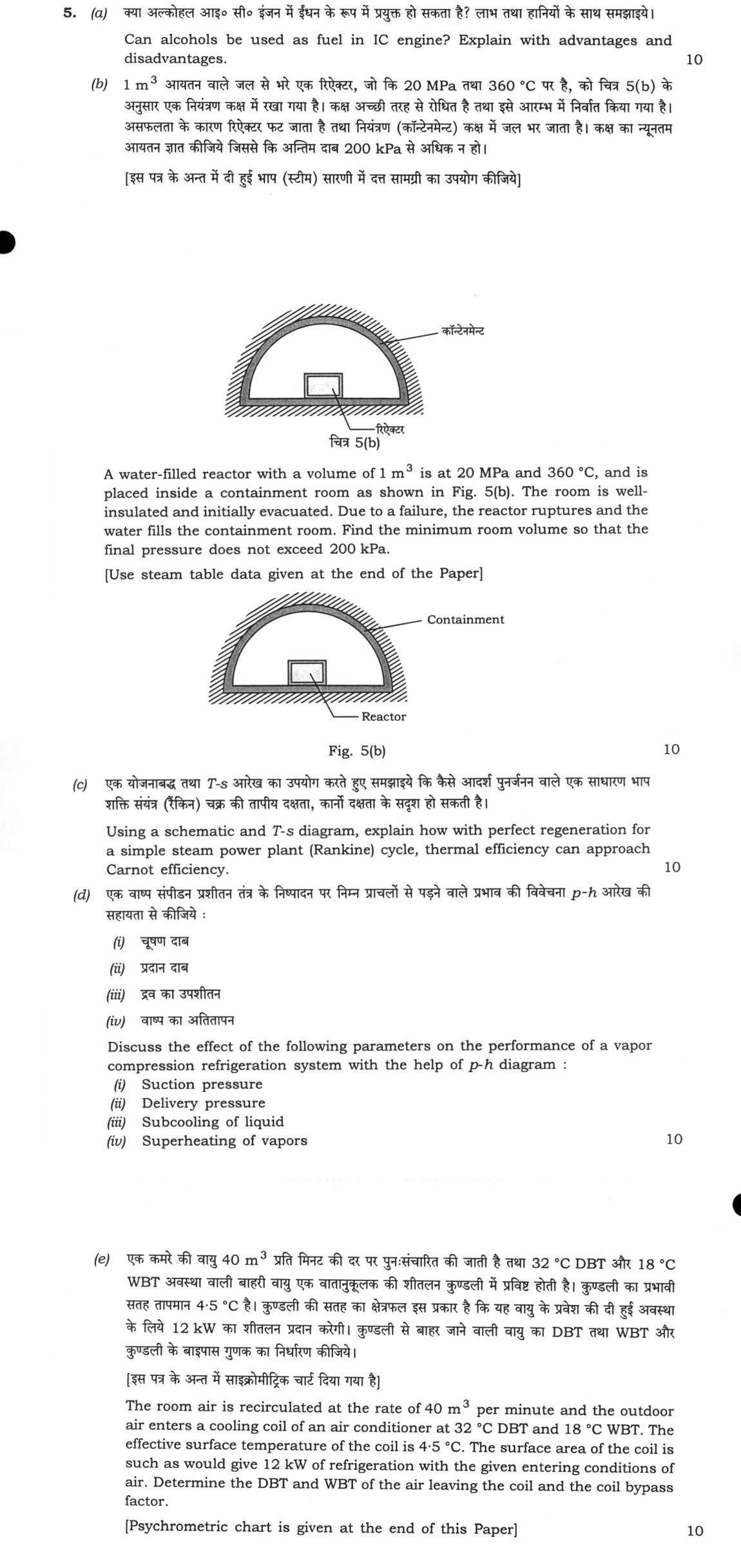
A water-filled reactor with a volume of 1 m³ is at 20 MPa and 360 °C, and is placed inside a containment room as shown in Fig. 5(b). The room is well-insulated and initially evacuated. Due to a failure, the reactor ruptures and the water fills the containment room. Find the minimum room volume so that the final pressure does not exceed 200 kPa. [Use steam table data given at the end of the Paper] 10 marks
Using a schematic and T-s diagram, explain how with perfect regeneration for a simple steam power plant (Rankine) cycle, thermal efficiency can approach Carnot efficiency. 10 marks
Discuss the effect of the following parameters on the performance of a vapor compression refrigeration system with the help of p-h diagram: (i) Suction pressure (ii) Delivery pressure (iii) Subcooling of liquid (iv) Superheating of vapors 10 marks
The room air is recirculated at the rate of 40 m³ per minute and the outdoor air enters a cooling coil of an air conditioner at 32 °C DBT and 18 °C WBT. The effective surface temperature of the coil is 4·5 °C. The surface area of the coil is such as would give 12 kW of refrigeration with the given entering conditions of air. Determine the DBT and WBT of the air leaving the coil and the coil bypass factor. [Psychrometric chart is given at the end of this Paper] 10 marks
हिंदी में प्रश्न पढ़ें
क्या अल्कोहल आइ० सी० इंजन में ईंधन के रूप में प्रयुक्त हो सकता है? लाभ तथा हानियों के साथ समझाइये। (10 अंक)
1 m³ आयतन वाले जल से भरे एक रिएक्टर, जो कि 20 MPa तथा 360 °C पर है, को चित्र 5(b) के अनुसार एक नियंत्रण कक्ष में रखा गया है। कक्ष अच्छी तरह से रोधित है तथा इसे आरंभ में निर्वात किया गया है। असफलता के कारण रिएक्टर फट जाता है तथा नियंत्रण (कंटेनमेंट) कक्ष में जल भर जाता है। कक्ष का न्यूनतम आयतन ज्ञात कीजिये जिससे कि अंतिम दाब 200 kPa से अधिक न हो। [इस पत्र के अंत में दी हुई भाप (स्टीम) सारणी में दत्त सामग्री का उपयोग कीजिये] (10 अंक)
एक योजनाबद्ध तथा T-s आरेख का उपयोग करते हुए समझाइये कि कैसे आदर्श पुनर्जनन वाले एक साधारण भाप शक्ति संयंत्र (रैंकिन) चक्र की तापीय दक्षता, कार्नो दक्षता के सदृश हो सकती है। (10 अंक)
एक वाष्प संपीडन प्रशीतन तंत्र के निष्पादन पर निम्न प्राचलों से पड़ने वाले प्रभाव की विवेचना p-h आरेख की सहायता से कीजिये: (i) चूषण दाब (ii) प्रदान दाब (iii) द्रव का उपशीतन (iv) वाष्प का अतितापन (10 अंक)
एक कमरे की वायु 40 m³ प्रति मिनट की दर पर पुनःसंचारित की जाती है तथा 32 °C DBT और 18 °C WBT अवस्था वाली बाहरी वायु एक वातानुकूलक की शीतलन कुण्डली में प्रविष्ट होती है। कुण्डली का प्रभावी सतह तापमान 4·5 °C है। कुण्डली की सतह का क्षेत्रफल इस प्रकार है कि यह वायु के प्रवेश की दी हुई अवस्था के लिये 12 kW का शीतलन प्रदान करेगा। कुण्डली से बाहर जाने वाली वायु का DBT तथा WBT और कुण्डली के बाइपास गुणक का निर्धारण कीजिये। [इस पत्र के अंत में साइक्रोमीट्रिक चार्ट दिया गया है] (10 अंक)
The figure this question refers to, in words
The question paper is a scan and the diagram did not survive as text. This is the figure as read from the original page — every component, value and label — so the question can be worked from the text below.
(b) A schematic diagram labeled 'Fig. 5(b)' showing a cross-section of a containment room. The room has a semi-circular top and a flat bottom, with the walls indicated by hatching. Inside the room, there is a small rectangular box labeled 'Reactor'. A label 'Containment' points to the outer wall of the room. The reactor is positioned centrally on the floor of the containment room.
Model answer
Written by UPSC Answer Check against this question's marking rubric, to the expected length. UPSC does not publish answers for Mains — this is one way to score well, not an official key.
Alcohols as IC-engine fuels. Methanol and ethanol can be used in spark-ignition engines directly or blended, and in compression-ignition engines with cetane improvers or in dual-fuel mode. Their oxygen content promotes more complete combustion, giving lower CO, hydrocarbons, particulate matter and SOx compared with gasoline or diesel. Ethanol and methanol have high octane numbers, allowing higher compression ratios, leaner operation and reduced knocking; in SI engines this permits advanced timing and higher brake mean effective pressure, while in CI engines the low cetane number must be corrected by additives, pilot diesel or dual-fuel injection. Bioethanol also has lower net carbon intensity. The disadvantages are lower volumetric energy density (ethanol about 24 MJ/L and methanol about 15.5 MJ/L against gasoline about 32 MJ/L), so more fuel is needed for the same power and range falls. Their high latent heat of vaporisation makes cold starting difficult, they are hygroscopic, and they can corrode metals and degrade some seals and elastomers. India’s ethanol-blending programme, moving from E10 toward E20 and including E85 flex-fuel trials, shows that blending is practical, but high blending levels require engine calibration, fuel-system compatibility and supply-chain safeguards.
Ruptured reactor containment. The initial water is compressed liquid at 20 MPa and 360 °C; using the supplied table, v1≈0.0015 m³/kg and u1≈1700 kJ/kg, so m=1/v1≈667 kg. The 1 m³ is the initial water volume; after rupture the same mass occupies the room. The room is insulated and initially evacuated, so the rupture is a free expansion with no heat, work, kinetic or potential energy change; no flow work is done on the surroundings, and hence m u1=m u2 and u2=u1=1700 kJ/kg. For the minimum room volume the final pressure is exactly 200 kPa, a saturated mixture. At 200 kPa, u_f=504.5 kJ/kg and u_fg=2025 kJ/kg, so x=(1700−504.5)/2025=0.590. With v_f=0.001061 m³/kg and v_g=0.8857 m³/kg, v2=v_f+x(v_g−v_f)=0.001061+0.590(0.8857−0.001061)=0.523 m³/kg. Therefore V_min=m v2≈667×0.523≈349 m³.
Regeneration and Carnot limit. The schematic is a Rankine cycle with boiler, turbine, condenser and pumps, plus open feedwater heaters fed by steam bled from the turbine at intermediate pressures. Each open heater is a heat exchanger in which feedwater is heated by condensing bleed steam; the drain from a higher-pressure heater is throttled to the next lower-pressure heater. On the T-s diagram, draw the saturation dome; the condenser is a horizontal line at T_min, the pump is a small vertical rise, the feedwater heating stages are short near-horizontal steps at rising temperatures, and the boiler heat addition is a horizontal line at T_max from saturated liquid to saturated vapour. In the unregenerated cycle the heat-addition line starts at a low feedwater temperature and extends to T_max; regeneration replaces that low-temperature portion by heat recovered from the turbine, leaving only a short high-temperature boiler section. As the number of stages increases, the feedwater enters the boiler closer to T_max, so the heat added in the boiler occurs over a narrower temperature range and tends to isothermal addition at T_max. The mean temperature of heat addition, T_h=Q_in/S_in, therefore approaches T_max. Since a reversible cycle’s efficiency is 1−T_c/T_h, the regenerated Rankine efficiency approaches 1−T_c/T_max, the Carnot efficiency.
p-h diagram effects. On the p-h diagram the basic cycle is evaporation at suction pressure, compression to delivery pressure, condensation, and throttling; state 1 is saturated or slightly superheated vapour at suction pressure, state 2 is the compressed discharge state, state 3 is liquid at delivery pressure, and state 4 is the throttled mixture. The refrigeration effect is the horizontal distance h1−h4, and compressor work is h2−h1. Increasing suction pressure raises evaporator temperature and moves state 1 to the right on the lower pressure line; h1 rises while h4 is nearly unchanged, so the refrigeration effect h1−h4 increases, compression ratio and specific volume fall, and COP generally improves. Increasing delivery pressure raises condenser temperature; h2 and h3 rise, h4 rises after throttling, so h1−h4 decreases while compressor work h2−h1 increases, lowering COP and raising discharge temperature. Subcooling the liquid lowers h3 and hence h4, increasing h1−h4 without changing compressor inlet state, so COP rises. Superheating the vapour moves state 1 further right; if the superheat is useful evaporator load, refrigeration effect increases and COP may improve, but if it is parasitic suction-line heat, the refrigeration effect does not increase while work rises, so COP falls.
Coil leaving state and bypass factor. No separate outdoor-air flow is printed; the determinate interpretation is that 40 m³/min is the total air flow through the coil. If it were only the recirculated room-air flow, the mixed-air condition would be indeterminate because the fresh-air flow and room condition are not given. At 32 °C DBT and 18 °C WBT, W1≈0.00714 kg/kg dry air and h1≈50.4 kJ/kg. The specific volume is v1≈0.878 m³/kg, so m_dot≈40/0.878=45.6 kg/min=0.760 kg/s. The coil gives 12 kW, so h2=50.4−12/0.760=34.6 kJ/kg. On the psychrometric chart, the exit point lies on the straight line joining the inlet point to the saturated 4.5 °C point because the leaving air is a mixture of bypassed inlet air and air cooled to the effective surface temperature. For perfect contact with a 4.5 °C effective surface, the air would leave saturated at 4.5 °C, with h_s≈17.5 kJ/kg. The fraction of air actually cooled is (h1−h2)/(h1−h_s)=15.8/32.9=0.480, so the bypass factor BF=1−0.480=0.520. Hence T2=BF×32+(1−BF)×4.5≈18.8 °C and W2≈BF×0.00714+(1−BF)×0.00518≈0.0062 kg/kg, giving a leaving WBT of about 12.2 °C. Thus the coil leaves air at approximately 18.8 °C DBT, 12.2 °C WBT, with a bypass factor of 0.52. Overall, alcohol fuels are feasible but constrained by energy density and materials, the containment volume follows from internal-energy conservation, regeneration approaches Carnot by raising the mean heat-addition temperature, refrigeration performance follows p-h state shifts, and the coil state is fixed by the energy balance and bypass model.
What "Explain" is asking you to do
Make the working of something clear — what sets it off, what follows from what, and what it produces. Explain is the Commission's mechanism word: it dominates the technical papers and the “explain why” stems, where the marks sit in the causal chain and not in the label.
Structure that answers it
State what it is → the initiating condition → the chain of cause, step by step → an instance where it plays out → what the chain produces
Where marks are lost
Describing what something looks like instead of why it works that way. Naming the stages without linking them reads as description too.
How this answer will be evaluated
Approach
Framework: UPSC Engineering Services (Preliminary/Mains) Technical Rubric. (a) explain: definition/context > points in order > small example > short close | (b) calculate: given > formula > substitution > result with units > interpretation | (c) explain: definition/context > points in order > small example > short close | (d) discuss: intro > 3-4 dimensions > example > balanced close | (e) calculate: given > formula > substitution > result with units > interpretation Full marks: Rigorous application of thermodynamic laws with clear diagrams and correct steam table/psychrometric data usage.
Key points expected
- Definition of alcohol fuels (methanol/ethanol)
- Advantages: high octane, low emissions
- Disadvantages: low energy density, corrosion
- Context of IC engine application
- Conservation of mass (m1 = m2)
- Conservation of energy (U1 = U2)
- Steam table lookup for initial state (20 MPa, 360°C)
- Final state properties at 200 kPa
Evaluation rubric
Each sub-part is marked on its own, against the marks and word limit printed on the paper.
- (a) Feasibility of alcohols as IC engine fuel with pros and cons. 10 marks
explain— definition/context → points in order → small example → short close
Must cover
- Definition of alcohol fuels (methanol/ethanol)
- Advantages: high octane, low emissions
- Disadvantages: low energy density, corrosion
- Context of IC engine application
Loses marks
- Generic 'clean fuel' claims without specifics
- Ignoring engine material compatibility
Earns more
- Mention of specific octane numbers
- Comparison with gasoline/diesel
Extra mark
- Reference to specific engine modifications
- (b) Minimum containment volume for final pressure ≤ 200 kPa. 10 marks
calculate— given → formula → substitution → result with units → interpretation
Must cover
- Conservation of mass (m1 = m2)
- Conservation of energy (U1 = U2)
- Steam table lookup for initial state (20 MPa, 360°C)
- Final state properties at 200 kPa
Loses marks
- Ignoring the volume of the reactor itself
- Using ideal gas law for high-pressure steam
Earns more
- Explicit calculation of specific volume (v)
- Clear unit conversion (MPa to kPa)
Extra mark
- Schematic of reactor and containment
- (c) How perfect regeneration makes Rankine efficiency approach Carnot. 10 marks
explain— definition/context → points in order → small example → short close
Must cover
- Schematic of Rankine cycle with regenerator
- T-s diagram showing heat addition at constant T
- Comparison of average heat addition temp
- Link to Carnot efficiency limit
Loses marks
- Missing T-s diagram
- Confusing regeneration with reheat
Earns more
- Labelled states on T-s diagram
- Mention of feedwater preheating
Extra mark
- Equation for efficiency improvement
- (d) Effect of 4 parameters on VCR performance using p-h diagram. 10 marks
discuss— intro → 3-4 dimensions → example → balanced close
Must cover
- p-h diagram with cycle lines
- Effect of suction pressure on COP
- Effect of delivery pressure on COP
- Effect of subcooling and superheating
Loses marks
- No p-h diagram provided
- Confusing subcooling with superheating
Earns more
- Quantitative trend (increase/decrease)
- Impact on compressor work
Extra mark
- Mention of specific refrigerant properties
- (e) Leaving air DBT/WBT and coil bypass factor. 10 marks
calculate— given → formula → substitution → result with units → interpretation
Must cover
- Energy balance for cooling load (12 kW)
- Psychrometric chart usage for state points
- Bypass factor (BPF) formula application
- Calculation of leaving state properties
Loses marks
- Ignoring the recirculation rate
- Incorrect BPF formula usage
Earns more
- Clear plotting of states on chart
- Consistent units (kW vs kJ/kg)
Extra mark
- Calculation of mass flow rate explicitly
Practice this exact question
Write your answer and it is marked point by point against the model answer above — what you covered, what you missed, what you got wrong.
Evaluate my answer →More from Mechanical Engineering 2022 Paper II
- Q2 (a) 10 g of water at 20 °C is converted into ice at –10 °C at constant atmospheric pressu…
- Q3 (a) (i) How do the specific work output and efficiency vary with pressure ratio in a gas…
- Q4 (a) A single-stage impulse turbine rotor has a mean blade ring diameter of 500 mm and rot…
- Q5 (a) Can alcohols be used as fuel in IC engine? Explain with advantages and disadvantages.…
- Q6 (a) A four-cylinder diesel engine with swept volume of 0·98 litre is tested on a performa…
- Q7 (a) (i) Briefly discuss HC, CO and NOₓ emission formation in SI engine. Explain the depen…
- Q8 (a) A VCR cycle refrigerator driven by a 60 kW compressor has a COP of 6·0. The enthalpie…