Paper II — Q3
(a) Heat is generated in a stainless steel plate (thermal conductivity = 22 W/m-K) of thickness 1 cm, at a uniform rate of 600…
Heat is generated in a stainless steel plate (thermal conductivity = 22 W/m-K) of thickness 1 cm, at a uniform rate of 600 MW/m³. The left side of the plate is maintained at 200 °C and the right side is maintained at 100 °C. What will be the (i) temperature distribution across the plate, (ii) location and value of maximum temperature and (iii) heat flux from both sides of the plate and its direction? Assume one-dimensional, steady-state heat conduction. 20 marks
A combination of a heat engine driving a heat pump (see the figure) takes waste energy at 50 °C as a source, Q̇W1, to the heat engine rejecting heat at 30 °C. The remainder, Q̇W2, goes into the heat pump that delivers Q̇H at 150 °C. If the total waste energy is 5 MW, find the rate of energy delivered at the higher temperature. Assume heat engine and heat pump as reversible : 20 marks
A centrifugal compressor delivers 1·25 kg/s of air while running at 6000 r.p.m. The diameters at the inlet and outlet are 0·5 m and 1 m respectively. The power input factor is 1·04, while the slip factor is unity. The power consumed by the compressor is 50 kW. State the type of impeller used, whether forward, radial or backward curved. Draw velocity triangles. Assume no prewhirl at the inlet. 10 marks
हिंदी में प्रश्न पढ़ें
1 cm मोटाई की एक जंगरोधी इस्पात पट्टिका (ऊष्मा चालकता = 22 W/m-K) में 600 MW/m³ की एकसमान दर से ऊष्मा उत्पन्न होती है। पट्टिका के बायीं ओर का तापमान 200 °C पर स्थिर बनाए रखा जाता है और दाहिनी ओर को 100 °C पर स्थिर बनाए रखा जाता है। (i) पट्टिका में तापमान वितरण, (ii) अधिकतम तापमान का स्थान और मान क्या होगा तथा (iii) पट्टिका के दोनों ओर से ऊष्मा फ्लक्स और उसकी दिशा क्या होगी? एक-आयामी, स्थायी-दशा ऊष्मा चालन मान लीजिए। (20 अंक)
ऊष्मा पम्प चलाने वाले ऊष्मा इंजन का एक संयोजन (चित्र देखिए) 50 °C पर अपशिष्ट ऊर्जा को एक स्रोत, Q̇W1, के रूप में, 30 °C पर ऊष्मा परित्याग करने वाले ऊष्मा इंजन में ले जाता है। शेष, Q̇W2, ऊष्मा पम्प में चली जाती है जो 150 °C पर Q̇H प्रदान करता है। यदि कुल अपशिष्ट ऊर्जा 5 MW है, तो उच्च तापमान पर वितरित ऊर्जा की दर ज्ञात कीजिए। ऊष्मा इंजन और ऊष्मा पम्प को प्रतिक्रम्य मान लीजिए : (20 अंक)
एक अपकेन्द्री संपीडक 6000 r.p.m. पर चलते समय 1·25 kg/s वायु प्रदान करता है। अन्तर्गम तथा निर्गम पर व्यास क्रमशः: 0·5 m और 1 m हैं। शक्ति निवेश गुणक 1·04 है, जबकि सर्पण गुणक इकाई है। संपीडक द्वारा खपत की गई शक्ति 50 kW है। उपयोग किए गए प्रणोदक का प्रकार बताइए, चाहे वह अग्र, विप्र या पश्च वक्र है। वेग त्रिभुज बनाइए। मान लीजिए कि अन्तर्गम पर कोई पूर्व-आवर्त नहीं है। (10 अंक)
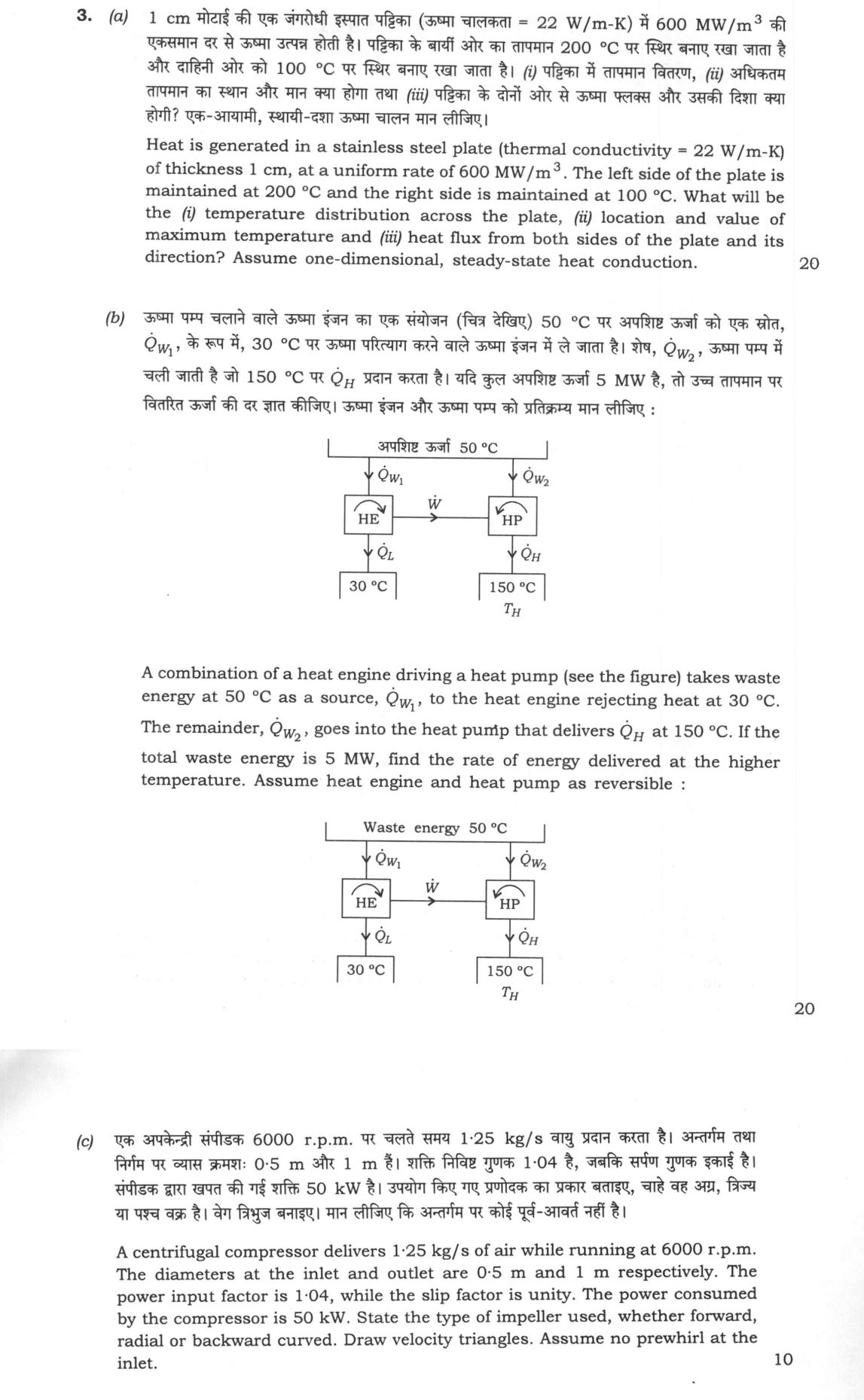
The figure this question refers to, in words
The question paper is a scan and the diagram did not survive as text. This is the figure as read from the original page — every component, value and label — so the question can be worked from the text below.
(b) A schematic diagram of a thermodynamic system consisting of a Heat Engine (HE) and a Heat Pump (HP) connected in series. A horizontal line at the top represents a source of 'Waste energy 50 °C'. Two vertical arrows point downwards from this line into the system: the left arrow is labeled Qdot_W1 and enters the top of the HE block; the right arrow is labeled Qdot_W2 and enters the top of the HP block. A horizontal arrow labeled Wdot points from the right side of the HE block to the left side of the HP block, indicating work transfer from the engine to the pump. From the bottom of the HE block, a vertical arrow labeled Qdot_L points downwards to a label '30 °C'. From the bottom of the HP block, a vertical arrow labeled Qdot_H points downwards to a label '150 °C' with the symbol T_H underneath.
Model answer
Written by UPSC Answer Check against this question's marking rubric, to the expected length. UPSC does not publish answers for Mains — this is one way to score well, not an official key.
(a) Let x be measured from the left face, 0 ≤ x ≤ L, L = 0.01 m. The model is steady one-dimensional conduction with constant k and uniform generation; the faces are isothermal. Fourier’s law plus the local energy balance gives k d²T/dx² + qgen = 0, with qgen = 600×10⁶ W/m³ and k = 22 W/m-K. Integrating twice: T(x) = -qgen x²/(2k) + C₁x + C₂. Boundary conditions T(0)=200 °C and T(L)=100 °C give C₂=200 and C₁ = [(100-200)+qgen L²/(2k)]/L. Now qgen L²/(2k) = (600×10⁶)(0.01)²/(2×22) = 15000/11 K, so C₁ = (13900/11)/0.01 = 1,390,000/11 K/m.
- (i) T(x) = 200 + (1,390,000/11)x - (150,000,000/11)x² °C, x in m.
- (ii) The maximum occurs where dT/dx=0. Thus x_max = C₁/(qgen/k) = (1,390,000/11)/(300,000,000/11) = 139/30000 m = 4.633×10⁻³ m from the left face. The parabola is concave downward, so this is a maximum. T_max = 200 + (qgen/(2k))x_max² = 200 + (600×10⁶/44)(19321/900×10⁶) = 200 + (2/3)(19321/44) = 200 + 19321/66 = 492.74 °C.
- (iii) Take positive x to the right. Heat flux is q_x = -k dT/dx. At x=0, q_x = -22(1,390,000/11) = -2.78×10⁶ W/m², so 2.78 MW/m² leaves the plate to the left. At x=L, dT/dx = 1,390,000/11 - 3,000,000/11 = -1,610,000/11 K/m, so q_x = +3.22×10⁶ W/m², i.e. 3.22 MW/m² leaves the plate to the right. The two fluxes sum to 6.00 MW/m² = qgen L.
(b) Use the first law and reversible entropy balance. Convert to kelvin: T0=323.15 K, TL=303.15 K, TH=423.15 K. For the reversible heat engine, Ẇ = Q̇W₁(1 - TL/T0) = Q̇W₁(20/323.15). For the reversible heat pump, Q̇W₂/T0 = Q̇H/TH, so Q̇H = Q̇W₂(TH/T0). Its energy balance gives Ẇ = Q̇H - Q̇W₂ = Q̇W₂(TH/T0 - 1) = Q̇W₂(100/323.15). Equating the work: Q̇W₁(20/323.15) = Q̇W₂(100/323.15), so Q̇W₁ = 5Q̇W₂. With Q̇W₁ + Q̇W₂ = 5 MW, Q̇W₂ = 5/6 MW and Q̇W₁ = 25/6 MW. Hence Q̇H = (5/6)(423.15/323.15) = 1.091 MW.
(c) Use Euler’s turbomachinery equation. N = 6000 r.p.m. = 100 rps. Blade speeds are U1 = π(0.5)(100) = 157.1 m/s, U2 = π(1.0)(100) = 314.2 m/s. No prewhirl gives Cw1=0. With power input factor φ=1.04, P = φ ṁ U2 Cw2, so Cw2 = 50,000/(1.04×1.25×314.2) = 5000/(13π) = 122.4 m/s. The specific shaft work is 50/1.25 = 40.0 kJ/kg; the Euler work is U2Cw2 = 38.46 kJ/kg, consistent with φ=1.04. Slip factor unity means no additional slip correction is applied; it does not force Cw2=U2.
Because 0 < Cw2 < U2, the relative outlet velocity has a tangential component opposite to rotation. The impeller is therefore backward curved.
Velocity triangles:
- Inlet: U1 = 157.1 m/s, Cw1 = 0; C1 is drawn perpendicular to U1, and W1 closes the triangle.
- Outlet: U2 = 314.2 m/s, Cw2 = 122.4 m/s; Cm2 is not fixed by the data. W2 has tangential component Cw2 - U2 = -191.7 m/s and radial component Cm2. If β₂ is measured from the backward tangent, tan β₂ = Cm2/(U2 - Cw2) = Cm2/191.7; a numerical β₂ would require Cm2, so it is not invented.
What "Calculate" is asking you to do
Apply the standard formula or schedule to data the question has already supplied — a table of readings, cost records, a balance sheet — and produce the number. The method is rarely in doubt; the marks sit in the named intermediate quantities, each of which has to appear as a labelled line.
Structure that answers it
Data as given → formula or standard treatment, named → substitution → each intermediate, labelled → result with units
Where marks are lost
Omitting an intermediate the marking scheme pays for separately, or rounding at an intermediate line so the final figure drifts. In commerce and accountancy, any figure in a statement that no numbered working note supports is treated as unearned.
How this answer will be evaluated
Approach
(a) calculate: given > formula > substitution > result with units > interpretation | (b) calculate: given > formula > substitution > result with units > interpretation | (c) describe: define > structure or process in order > labelled diagram > significance Full marks: Complete derivations with all assumptions stated, correct units throughout, and physically meaningful interpretations of results.
Key points expected
- State governing 1D steady-state heat equation with generation
- Apply boundary conditions T(0)=200°C and T(L)=100°C
- Derive parabolic temperature distribution equation
- Calculate heat flux at both surfaces with direction
- Apply Carnot efficiency to heat engine (50°C to 30°C)
- Apply Carnot COP to heat pump (30°C to 150°C)
- Relate work output of HE to work input of HP
- Calculate Q_H delivered at 150°C
Evaluation rubric
Each sub-part is marked on its own, against the marks and word limit printed on the paper.
- (a) Determine temperature distribution, maximum temperature location/value, and heat fluxes for a plate with internal heat generation. 20 marks
calculate— given → formula → substitution → result with units → interpretation
Must cover
- State governing 1D steady-state heat equation with generation
- Apply boundary conditions T(0)=200°C and T(L)=100°C
- Derive parabolic temperature distribution equation
- Calculate heat flux at both surfaces with direction
Loses marks
- Using linear temperature distribution without generation term
- Ignoring direction of heat flux at surfaces
- Plugging numbers without stating governing equation
Earns more
- Identify location of maximum temperature via dT/dx=0
- Verify energy balance between generation and conduction
- Sketch temperature profile across the plate
- Check dimensional consistency of heat generation term
Extra mark
- Compare with case of no internal generation
- Discuss effect of changing boundary temperatures
- (b) Find rate of energy delivered at higher temperature for reversible heat engine driving heat pump system. 20 marks
calculate— given → formula → substitution → result with units → interpretation
Must cover
- Apply Carnot efficiency to heat engine (50°C to 30°C)
- Apply Carnot COP to heat pump (30°C to 150°C)
- Relate work output of HE to work input of HP
- Calculate Q_H delivered at 150°C
Loses marks
- Using Celsius temperatures in Carnot equations
- Confusing COP of heat pump with efficiency
- Not relating work between HE and HP correctly
Earns more
- Convert all temperatures to Kelvin before calculations
- Show energy balance for the combined system
- Label all heat and work flows on schematic
- Verify second law compliance for both cycles
Extra mark
- Calculate overall system efficiency
- Discuss practical limitations of reversible assumption
- (c) Determine impeller blade type and draw velocity triangles for centrifugal compressor. 10 marks
describe— define → structure or process in order → labelled diagram → significance
Must cover
- Calculate blade velocities at inlet and outlet
- Determine whirl velocity from power equation
- Draw inlet and outlet velocity triangles
- Identify blade type from outlet triangle geometry
Loses marks
- Drawing velocity triangles without proper scaling
- Ignoring slip factor in outlet velocity calculation
- Misidentifying blade type from triangle geometry
Earns more
- Apply slip factor and power input factor correctly
- Show all velocity components on triangles
- Verify no prewhirl condition at inlet
- Calculate flow and whirl velocities explicitly
Extra mark
- Calculate Euler head or work done
- Discuss effect of slip factor on performance
Practice this exact question
Write your answer and it is marked point by point against the model answer above — what you covered, what you missed, what you got wrong.
Evaluate my answer →More from Mechanical Engineering 2023 Paper II
- Q1 (a) A 50 kg block of iron at 500 K is placed into open atmosphere which is at a temperatu…
- Q2 (a) A 15 m high cylinder with a cross-sectional area of 0.6 m² contains 3 m³ of liquid wa…
- Q3 (a) Heat is generated in a stainless steel plate (thermal conductivity = 22 W/m-K) of thi…
- Q4 (a) Considering an ideal, isentropic gas flow through a nozzle, show that choking will oc…
- Q5 (a) Show in the form of a table, how the increase in the following variables affects (inc…
- Q6 (a) The power output of a six-cylinder, four-stroke CI engine is absorbed by a hydraulic…