Paper II — Q6
(a) The power output of a six-cylinder, four-stroke CI engine is absorbed by a hydraulic dynamometer for which the law is P =…
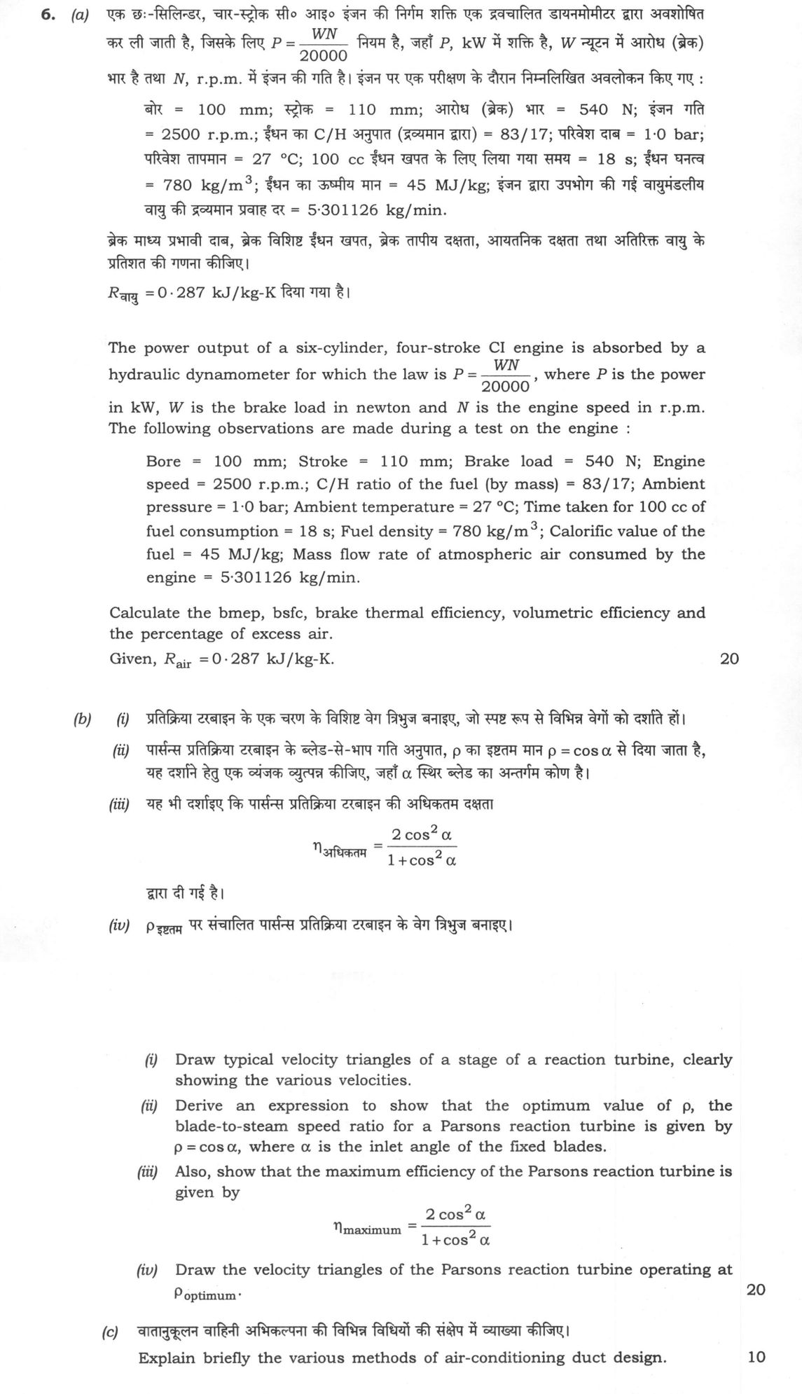
The power output of a six-cylinder, four-stroke CI engine is absorbed by a hydraulic dynamometer for which the law is P = WN/20000, where P is the power in kW, W is the brake load in newton and N is the engine speed in r.p.m. The following observations are made during a test on the engine: Bore = 100 mm; Stroke = 110 mm; Brake load = 540 N; Engine speed = 2500 r.p.m.; C/H ratio of the fuel (by mass) = 83/17; Ambient pressure = 1·0 bar; Ambient temperature = 27 °C; Time taken for 100 cc of fuel consumption = 18 s; Fuel density = 780 kg/m³; Calorific value of the fuel = 45 MJ/kg; Mass flow rate of atmospheric air consumed by the engine = 5·301126 kg/min. Calculate the bmep, bsfc, brake thermal efficiency, volumetric efficiency and the percentage of excess air. Given, R_air = 0·287 kJ/kg-K. 20 marks
Draw typical velocity triangles of a stage of a reaction turbine, clearly showing the various velocities. (ii) Derive an expression to show that the optimum value of ρ, the blade-to-steam speed ratio for a Parsons reaction turbine is given by ρ = cos α, where α is the inlet angle of the fixed blades. (iii) Also, show that the maximum efficiency of the Parsons reaction turbine is given by η_maximum = (2 cos² α)/(1 + cos² α). (iv) Draw the velocity triangles of the Parsons reaction turbine operating at ρ_optimum. 20 marks
Explain briefly the various methods of air-conditioning duct design. 10 marks
हिंदी में प्रश्न पढ़ें
एक छः-सिलिंडर, चार-स्ट्रोक सी। आई। इंजन की निगम शक्ति एक द्रवचालित डायनमोमीटर द्वारा अवशोषित कर ली जाती है, जिसके लिए P = WN/20000 नियम है, जहाँ P, kW में शक्ति है, W न्यूटन में आरोध (ब्रेक) भार है तथा N, r.p.m. में इंजन की गति है। इंजन पर एक परीक्षण के दौरान निम्नलिखित अवलोकन किए गए: बोर = 100 mm; स्ट्रोक = 110 mm; आरोध (ब्रेक) भार = 540 N; इंजन गति = 2500 r.p.m.; ईंधन का C/H अनुपात (द्रव्यमान द्वारा) = 83/17; परिवेश दाब = 1·0 bar; परिवेश तापमान = 27 °C; 100 cc ईंधन खपत के लिए लिया गया समय = 18 s; ईंधन घनत्व = 780 kg/m³; ईंधन का ऊष्मीय मान = 45 MJ/kg; इंजन द्वारा उपभोग की गई वायुमंडलीय वायु की द्रव्यमान प्रवाह दर = 5·301126 kg/min. ब्रेक माध्य प्रभावी दाब, ब्रेक विशिष्ट ईंधन खपत, ब्रेक तापीय दक्षता, आयतनिक दक्षता तथा अतिरिक्त वायु के प्रतिशत की गणना कीजिए। R_वायु = 0·287 kJ/kg-K दिया गया है। (20 अंक)
प्रतिक्रिया टरबाइन के एक चरण के विरुद्ध वेग त्रिभुज बनाइए, जो स्पष्ट रूप से विभिन्न वेगों को दर्शाते हों। (ii) पार्संस प्रतिक्रिया टरबाइन के ब्लेड-से-भाप गति अनुपात, ρ का इष्टत मान ρ = cos α से दिया जाता है, यह दर्शाने हेतु एक व्यंजक व्युत्पन्न कीजिए, जहाँ α स्थिर ब्लेड का अंतर्गामी कोण है। (iii) यह भी दर्शाइए कि पार्संस प्रतिक्रिया टरबाइन की अधिकतम दक्षता η_अधिकतम = (2cos²α)/(1+cos²α) द्वारा दी गई है। (iv) ρ_इष्टत पर संचालित पार्संस प्रतिक्रिया टरबाइन के वेग त्रिभुज बनाइए। (20 अंक)
वातानुकूलन वाहिनी अभिकल्पना की विभिन्न विधियों की संक्षेप में व्याख्या कीजिए। (10 अंक)
Model answer
Written by UPSC Answer Check against this question's marking rubric, to the expected length. UPSC does not publish answers for Mains — this is one way to score well, not an official key.
(a) Brake power from dynamometer law: P = W N / 20000 = 540 × 2500 / 20000 = 67.5 kW.
Swept volume per cylinder: V_s = (π/4) d² L = (π/4)(0.100 m)²(0.110 m) = 0.000275π m³.
Total swept volume rate for a four-stroke, 6-cylinder engine: V̇_s = i V_s N / (2 × 60) = 6 × 0.000275π × 2500 / 120 = 0.107992 m³/s.
Brake mean effective pressure: bmep = BP / V̇_s = 67.5 kW / 0.107992 m³/s = 625.04 kPa = 6.250 bar.
Fuel mass flow rate: ṁ_f = (100 × 10⁻⁶ m³ / 18 s) × 780 kg/m³ = 0.004333 kg/s = 15.6 kg/h.
Brake specific fuel consumption: bsfc = ṁ_f per hour / BP = 15.6 kg/h / 67.5 kW = 0.2311 kg/kWh = 231.1 g/kWh.
Brake thermal efficiency: Heat input = ṁ_f × CV = 0.004333 kg/s × 45000 kJ/kg = 195 kW. η_bt = BP / Heat input = 67.5 / 195 = 0.34615 = 34.62%.
Air density at ambient conditions: ρ_a = P / (R T) = 100 kPa / (0.287 kJ/kg-K × 300 K) = 1.16144 kg/m³.
Theoretical air mass flow if swept volume were filled at ambient conditions: ṁ_th = ρ_a V̇_s × 60 = 1.16144 × 0.107992 × 60 = 7.5256 kg/min.
Volumetric efficiency: η_v = ṁ_actual / ṁ_th = 5.301126 / 7.5256 = 0.7044 = 70.44%.
Stoichiometric air-fuel ratio for C = 0.83, H = 0.17: O₂ required = (8/3)(0.83) + 8(0.17) = 3.5733 kg O₂/kg fuel. Air required = 3.5733 / 0.232 = 15.402 kg air/kg fuel.
Actual air-fuel ratio: A/F = 5.301126 kg/min / 0.26 kg/min = 20.389 kg air/kg fuel.
Percentage excess air: = (20.389 − 15.402) / 15.402 × 100 = 32.38%.
(b)(i) For a reaction stage, the moving-blade inlet and outlet velocity triangles are drawn with U = blade speed, C₁ = absolute inlet velocity, Vr₁ = relative inlet velocity, C₂ = absolute outlet velocity, Vr₂ = relative outlet velocity. Whirl and flow components are Cw = C cos α, Cf = C sin α. Inlet triangle: U horizontal; C₁ at angle α to U; Vr₁ = C₁ − U. Outlet triangle: Vr₂ is relative outlet; C₂ = Vr₂ + U; C₂ at angle β to U. Sketch: `` Inlet: Outlet: C1 Vr2 /| /| Cf1/ |α / |β /__|____ U /__|____ U Vr1 C2 ``
(b)(ii) For a Parsons turbine, degree of reaction R = 1/2, so fixed and moving blades are identical and velocity triangles are symmetrical. Hence Vr₂ = C₁ and Vr₁ = C₂.
Let C₁ be the absolute velocity entering the moving blades, α the fixed-blade angle, and U the blade speed. Whirl at inlet: Cw₁ = C₁ cos α.
At outlet, the relative whirl of Vr₂ is C₁ cos α opposite to U, so absolute whirl: Cw₂ = U − C₁ cos α.
Work done per kg: W = U(Cw₁ − Cw₂) = U[C₁ cos α − (U − C₁ cos α)] W = U(2C₁ cos α − U). ...(1)
Outlet absolute velocity: C₂² = (U − C₁ cos α)² + (C₁ sin α)² C₂² = C₁² + U² − 2U C₁ cos α.
Energy supplied per kg: E = W + C₂²/2 = C₁²/2 + U C₁ cos α − U²/2. ...(2)
Efficiency: η = W/E = [U(2C₁ cos α − U)] / [C₁²/2 + U C₁ cos α − U²/2].
Put ρ = U/C₁. Then: η = [2ρ(2 cos α − ρ)] / [1 + 2ρ cos α − ρ²].
Differentiate with respect to ρ: dη/dρ = 0 ⇒ ρ = cos α.
Thus the optimum blade-to-steam speed ratio for a Parsons reaction turbine is ρ = cos α.
(b)(iii) Substitute ρ = cos α in the efficiency expression: η_max = [2 cos α(2 cos α − cos α)] / [1 + 2 cos² α − cos² α] η_max = 2 cos² α / (1 + cos² α).
Hence proved: η_maximum = (2 cos² α)/(1 + cos² α).
(b)(iv) At ρ_optimum = cos α, U = C₁ cos α. Therefore the inlet relative velocity Vr₁ is axial, of magnitude C₁ sin α. The outlet absolute velocity C₂ is also axial, of magnitude C₁ sin α. The outlet relative velocity Vr₂ = C₁ makes an angle α with the negative direction of U. Thus the velocity triangles are right triangles: Inlet: U horizontal; C₁ at angle α; Vr₁ vertical (axial). Outlet: U horizontal; Vr₂ at angle α to the negative U direction; C₂ vertical (axial).
(c) Various methods of air-conditioning duct design are:
- Velocity reduction method: Assumed air velocities are selected for successive duct sections. Duct area is found from A = Q/V. Friction losses are calculated and branches are balanced by dampers. It is simple but may require extra throttling.
- Equal friction method: A constant friction loss per unit length, usually in Pa/m, is chosen for the whole system or main duct. Duct sizes are selected so that each section has the same friction gradient. Total pressure drop is then found along the critical path. It is widely used for simple low-velocity systems.
- Static regain method: Ducts are sized so that the static pressure regained due to velocity reduction in one section balances the friction loss in the following section. It gives better balance and lower fan power in large systems, but calculations are more involved.
- Velocity pressure method: Both friction and dynamic losses are expressed in terms of velocity pressure. The duct is sized to meet a specified total pressure loss. It is useful for systems with many fittings and transitions.
- T-method: An optimization method in which duct sizes are selected to minimize total owning and operating cost, including fan energy. It requires iterative calculation and is used in large HVAC designs.
- Equivalent resistance method: Branch resistances are converted into equivalent resistances and ducts are sized to equalize pressure drops. It is convenient for balanced multi-branch layouts.
All methods are applied for standard air density, and dampers or balancing devices are finally used to trim the actual airflow.
What "Calculate" is asking you to do
Apply the standard formula or schedule to data the question has already supplied — a table of readings, cost records, a balance sheet — and produce the number. The method is rarely in doubt; the marks sit in the named intermediate quantities, each of which has to appear as a labelled line.
Structure that answers it
Data as given → formula or standard treatment, named → substitution → each intermediate, labelled → result with units
Where marks are lost
Omitting an intermediate the marking scheme pays for separately, or rounding at an intermediate line so the final figure drifts. In commerce and accountancy, any figure in a statement that no numbered working note supports is treated as unearned.
How this answer will be evaluated
Approach
(a) calculate: given > formula > substitution > result with units > interpretation | (b) derive: given > assumptions > stepwise derivation > result > check | (c) explain: definition/context > points in order > small example > short close Full marks: Complete derivations with clear diagrams; all calculations shown with units; concise and accurate explanations.
Key points expected
- Calculate Brake Power using P = WN/20000
- Determine fuel mass flow rate from time and density
- Calculate bmep using BP, N, and cylinder volume
- Compute volumetric efficiency using actual vs theoretical air
- Draw velocity triangles for fixed and moving blades
- Derive work done per kg of steam expression
- Differentiate work expression to find optimum ρ
- Substitute ρ = cos α to find maximum efficiency
Evaluation rubric
Each sub-part is marked on its own, against the marks and word limit printed on the paper.
- (a) Compute bmep, bsfc, brake thermal efficiency, volumetric efficiency, and excess air percentage. 20 marks
calculate— given → formula → substitution → result with units → interpretation
Must cover
- Calculate Brake Power using P = WN/20000
- Determine fuel mass flow rate from time and density
- Calculate bmep using BP, N, and cylinder volume
- Compute volumetric efficiency using actual vs theoretical air
Loses marks
- Plugging numbers without stating governing equations
- Omitting units in intermediate or final results
- Incorrect conversion of fuel volume to mass
Earns more
- Show step-by-step unit conversions (cc to m³, s to min)
- State stoichiometric air-fuel ratio for C/H 83/17
- Calculate theoretical air volume at ambient conditions
- Interpret physical meaning of excess air percentage
Extra mark
- Provide a labelled p-V diagram for the CI cycle
- Include a table summarising all calculated parameters
- (b) Derive optimum blade speed ratio and maximum efficiency for Parsons turbine. 20 marks
derive— given → assumptions → stepwise derivation → result → check
Must cover
- Draw velocity triangles for fixed and moving blades
- Derive work done per kg of steam expression
- Differentiate work expression to find optimum ρ
- Substitute ρ = cos α to find maximum efficiency
Loses marks
- Missing velocity triangle diagrams or unmarked states
- Skipping the differentiation step in derivation
- Confusing blade angle α with steam angle β
Earns more
- Clearly label all velocity components (C1, C2, V1, V2, u)
- Show the condition for maximum work (V1x = V2x)
- Draw specific triangles for ρ_optimum case
- State assumptions: 50% reaction, symmetric blades
Extra mark
- Include a T-s diagram for the stage
- Compare efficiency with impulse turbine at same α
- (c) Briefly explain the various methods of air-conditioning duct design. 10 marks
explain— definition/context → points in order → small example → short close
Must cover
- Define the objective of duct design (pressure drop)
- List at least 3-4 common duct design methods
- Explain the principle of one method (e.g. equal friction)
- Mention the trade-off between cost and performance
Loses marks
- Listing methods without explaining any principle
- Confusing duct design with load calculation
- Vague or generic statements without technical detail
Earns more
- Compare static regain vs equal friction methods
- Mention the impact of duct size on noise
- Reference standard design guidelines (e.g. ASHRAE)
- Provide a simple example of duct sizing
Extra mark
- Include a schematic of a duct system layout
- Mention specific software used for duct design
Practice this exact question
Write your answer and it is marked point by point against the model answer above — what you covered, what you missed, what you got wrong.
Evaluate my answer →More from Mechanical Engineering 2023 Paper II
- Q3 (a) Heat is generated in a stainless steel plate (thermal conductivity = 22 W/m-K) of thi…
- Q4 (a) Considering an ideal, isentropic gas flow through a nozzle, show that choking will oc…
- Q5 (a) Show in the form of a table, how the increase in the following variables affects (inc…
- Q6 (a) The power output of a six-cylinder, four-stroke CI engine is absorbed by a hydraulic…
- Q7 (a) A convergent-divergent nozzle receives steam at 5 bar, 250 °C and expands it isentrop…
- Q8 (a) An SI engine working on the Otto cycle has cylinder bore of 210 mm and stroke length…