Paper I — Q3
(a) (i) The recoil mechanism of a gun consists of a critically damped spring-damper system. The maximum permissible recoil…
The recoil mechanism of a gun consists of a critically damped spring-damper system. The maximum permissible recoil distance of the gun is specified as 0·5 m. If the initial recoil velocity of the gun is 10 m/s and the mass of the gun is 500 kg, determine the spring stiffness of the recoil mechanism and the critical damping coefficient of the damper. 10 marks
A punching press executes 10 holes per minute in a 25 mm thick plate. The diameter of each hole is 20 mm. The punch has a stroke of 60 mm and the punch moves with uniform velocity throughout. A flywheel is attached to the press and the mean speed of the flywheel is 25 m/s. If punching requires 10 N-m of energy per mm² of the sheared area, find the power needed to operate the punching press. Further determine the mass of the flywheel required if the total fluctuation of speed is restricted to 5% of the mean speed. 10 marks
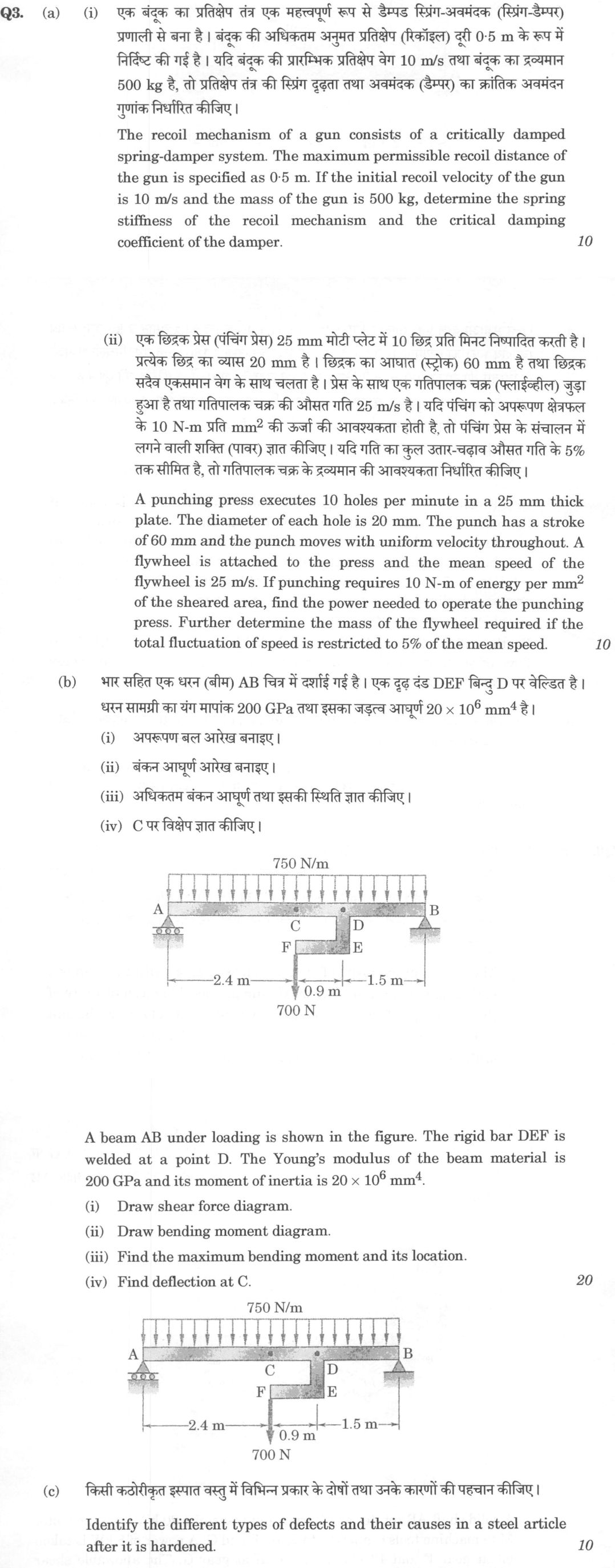
A beam AB under loading is shown in the figure. The rigid bar DEF is welded at a point D. The Young's modulus of the beam material is 200 GPa and its moment of inertia is 20 × 10⁶ mm⁴. Draw shear force diagram.
Draw bending moment diagram.
Find the maximum bending moment and its location.
Find deflection at C. 20 marks
Identify the different types of defects and their causes in a steel article after it is hardened. 10 marks
हिंदी में प्रश्न पढ़ें
एक बंदूक का प्रतिक्षेप तंत्र एक महत्वपूर्ण रूप से डैम्प्ड स्प्रिंग-अवमंदक (स्प्रिंग-डैम्पर) प्रणाली से बना है। बंदूक की अधिकतम अनुमत प्रतिक्षेप (रिकॉइल) दूरी 0·5 m के रूप में निर्दिष्ट की गई है। यदि बंदूक की प्रारंभिक प्रतिक्षेप वेग 10 m/s तथा बंदूक का द्रव्यमान 500 kg है, तो प्रतिक्षेप तंत्र की स्प्रिंग दृढ़ता तथा अवमंदक (डैम्पर) का कांतिक अवमंदन गुणांक निर्धारित कीजिए। (10 अंक)
एक छिद्रक प्रेस (पंचिंग प्रेस) 25 mm मोटी प्लेट में 10 छिद्र प्रति मिनट निष्पादित करती है। प्रत्येक छिद्र का व्यास 20 mm है। छिद्रक का आघात (स्ट्रोक) 60 mm है तथा छिद्रक सदैव एकसमान बेग के साथ चलता है। प्रेस के साथ एक गतिपालक चक्र (फ्लाइव्हील) जुड़ा हुआ है तथा गतिपालक चक्र की औसत गति 25 m/s है। यदि पंचिंग को अपरूपण क्षेत्रफल के 10 N-m प्रति mm² की ऊर्जा की आवश्यकता होती है, तो पंचिंग प्रेस के संचालन में लगने वाली शक्ति (पावर) ज्ञात कीजिए। यदि गति का कुल उतार-चढ़ाव औसत गति के 5% तक सीमित है, तो गतिपालक चक्र के द्रव्यमान की आवश्यकता निर्धारित कीजिए। (10 अंक)
भार सहित एक धरन (बीम) AB चित्र में दर्शाई गई है। एक दृढ़ दंड DEF बिंदु D पर वेल्डित है। धरन सामग्री का यंग मापांक 200 GPa तथा इसका जड़त्व आघूर्ण 20 × 10⁶ mm⁴ है। अपरूपण बल आरेख बनाइए।
बंकन आघूर्ण आरेख बनाइए।
अधिकतम बंकन आघूर्ण तथा इसकी स्थिति ज्ञात कीजिए।
C पर विस्थेप ज्ञात कीजिए। (20 अंक)
किसी कठोरीकृत इस्पात वस्तु में विभिन्न प्रकार के दोषों तथा उनके कारणों की पहचान कीजिए। (10 अंक)
The figure this question refers to, in words
The question paper is a scan and the diagram did not survive as text. This is the figure as read from the original page — every component, value and label — so the question can be worked from the text below.
(b) A mechanical assembly consisting of a solid shaft AB supported at both ends by bearings. The shaft rotates at 450 rpm and transmits 20 kW from a motor M to machine tools connected to gears F and G. The motor M is located between support A and gear F. The power is distributed such that 8 kW is taken off at gear F and 12 kW is taken off at gear G. The allowable shear stress for the shaft material is 55 MPa. The dimensions along the shaft are as follows: The distance from support A to the center of gear F is 150 mm. The distance from gear F to the center of gear D (where the motor is connected) is 225 mm. The distance from gear D to the center of gear G is 225 mm. The distance from gear G to support B is 150 mm. The pitch diameter of gear F is 60 mm. The pitch diameter of gear D is 100 mm. The pitch diameter of gear G is 60 mm. The question asks to determine the smallest permissible diameter of the shaft AB.
Model answer
Written by UPSC Answer Check against this question's marking rubric, to the expected length. UPSC does not publish answers for Mains — this is one way to score well, not an official key.
(a)(i) Use the critically damped single-degree-of-freedom solution. The equation of motion is m d²x/dt² + c dx/dt + kx = 0. Critical damping makes the characteristic roots equal, so c = 2√(mk) and the repeated root is r = -ω, where ω = √(k/m). With zero initial displacement and initial recoil velocity v₀ = 10 m/s, x(t) = (A + B t)e^(-ωt). The initial conditions give A = 0 and B = v₀, so x(t) = 10 t e^(-ωt). Differentiate: dx/dt = 10 e^(-ωt)(1 - ωt). Maximum recoil occurs when dx/dt = 0, so t = 1/ω. Substituting gives x_max = 10/(ω e). Given x_max = 0.5 m, ω = 10/(0.5 e) = 20/e s⁻¹. Hence k = mω² = 500(20/e)² = 200000/e² N/m ≈ 2.71×10⁴ N/m, and c = 2mω = 2(500)(20/e) = 20000/e N s/m ≈ 7.36×10³ N s/m. Check: x(0)=0, v(0)=10 m/s, and the peak is exactly 0.5 m. The spring stiffness is the minimum value that keeps the peak at 0.5 m. Valid for linear spring and damper, zero initial displacement, and exact critical damping.
(a)(ii) Use specific shearing energy and the flywheel energy-fluctuation relation. Sheared area per hole is Aₛ = π d t = π(20 mm)(25 mm) = 500π mm². Energy per hole is Eₚ = 10 N·m/mm² × 500π mm² = 5000π J. For 10 holes/min, average power is P = 10Eₚ/60 = 2500π/3 W ≈ 2.62 kW. This is mean shaft power; the flywheel supplies the short peak demand during each punch. For the flywheel, C = (ω_max - ω_min)/ω_mean = 0.05. The fluctuation energy is ΔE = ½I(ω_max² - ω_min²). If ω_mean is the arithmetic mean of ω_max and ω_min, this becomes ΔE = Iω_mean²C. With rim speed v = ωR and rim mass m, I = mR², so ΔE = mv²C. Assuming the punch velocity is the given mean flywheel rim speed, because no drive ratio is specified, punching time is tₚ = 0.060 m / 25 m/s = 3/1250 s. Motor energy during punching at average power is Eₘ = P tₚ = (2500π/3)(3/1250) = 2π J. Thus the flywheel must supply ΔE = Eₚ - Eₘ = 4998π J. Required rim mass is m = ΔE/(v²C) = 4998π/(25² × 0.05) = 19992π/125 kg ≈ 502 kg. The result assumes the flywheel mass is concentrated at the rim. If motor energy during the stroke is neglected, m = 160π kg, differing by 0.04%.
[(b)] The figure printed on the original question paper for this part could not be recovered from the scan, so this part is not answered here. (b)(i) The shear force diagram cannot be drawn because the supplied description is a shaft design problem, not the beam AB loading, support conditions, point C, or rigid bar DEF required by the question. (b)(ii) The bending moment diagram cannot be drawn for the same reason; no beam loads, spans, or support reactions are available. (b)(iii) The maximum bending moment and its location cannot be found without the load diagram and support conditions. (b)(iv) The deflection at C cannot be found without the load diagram, the position of C, and the beam geometry. The given E = 200 GPa and I = 20×10⁶ mm⁴ cannot be used without those data. No alternative beam data are used.
(c) Defects in a steel article after hardening and their causes:
- Quench cracks: rapid cooling produces large thermal gradients; martensite formation adds volume expansion and high internal stress. High carbon, high hardenability, sharp corners, thick sections, too aggressive quench, insufficient preheat, or mechanical restraint can initiate cracks.
- Warping or distortion: uneven cooling of asymmetric or unequal sections, non-uniform martensitic transformation, residual stresses, improper support during quenching, or thermal and mechanical stresses can bend or twist the part.
- Soft spots or incomplete hardening: insufficient austenitizing temperature or holding time, slow quench, decarburized surface, alloy segregation, improper quench medium, or local overheating that coarsens the structure can leave regions below required hardness.
- Decarburization: exposure to oxidizing or decarburizing atmosphere at high temperature, overheating, scale formation, or prolonged furnace residence removes surface carbon and reduces surface hardness and fatigue life.
- Oxidation and scaling: high austenitizing temperature, prolonged heating, oxygen or sulfur in the atmosphere, poor furnace control, or inadequate protective atmosphere forms scale and pits.
- Coarse grain growth: overheating or excessive holding time in the austenite range enlarges grains, reducing toughness, hardenability, and fatigue resistance.
- Residual stresses: non-uniform martensitic transformation, prior cold working, improper preheat, inadequate stress relief, or uneven section cooling leaves internal stresses that can cause later cracking or distortion.
- Hardness variation: uneven austenitizing, uneven cooling, varying section thickness, decarburization, alloy segregation, or incomplete transformation gives different hardness in different zones.
- Surface roughness or pits: scale, slag, furnace contamination, improper handling, or quench medium contamination can roughen the surface and create stress raisers.
- Internal cracks: high hardenability, high carbon, restrained cooling, prior inclusions, insufficient preheat, or excessive section thickness can produce subsurface or internal cracking.
- Temper cracks, if tempered after hardening: slow cooling from tempering, high hardenability, impurities, or excessive section thickness can cause cracking during temper.
- Temper embrittlement, if tempered: slow cooling through tempering ranges, impurities such as phosphorus, high hardenability, or excessive tempering time can reduce impact toughness.
What "Solve" is asking you to do
Choose the method, then carry it through to a final answer. Identifying what kind of problem this is and why that method applies is the first thing marked; a correct figure arrived at invisibly earns almost nothing.
Structure that answers it
Given data and what is required → method chosen, with the reason it applies → set-up (equation, circuit, free body, trial balance) → working, step by step → answer with units and any condition of validity
Where marks are lost
Doing the middle steps mentally and writing only the result. In mathematics papers, a further loss comes from giving a decimal where the exact value in surds or fractions was wanted, or from skipping the justification a part explicitly asks for.
How this answer will be evaluated
Approach
(a(i)) calculate: given > formula > substitution > result with units > interpretation | (a(ii)) calculate: given > formula > substitution > result with units > interpretation | (b) calculate: given > formula > substitution > result with units > interpretation | (c) enumerate: list the items in order > one line each > no commentary Full marks: All parts show complete method with governing equations, correct units, and physical interpretation.
Key points expected
- State critical damping condition c = 2√(km)
- Use x(t) = (A + Bt)e^(-ωt) for critical damping
- Apply initial conditions x(0)=0, v(0)=10 m/s
- Solve for k and c using x_max = 0.5 m
- Calculate sheared area = π × d × t
- Energy per punch = 10 N·m/mm² × sheared area
- Power = (Energy per punch × 10) / 60 s
- Use ΔE = (1/2)I(ω_max² - ω_min²) for flywheel
Evaluation rubric
Each sub-part is marked on its own, against the marks and word limit printed on the paper.
- (a(i)) Determine spring stiffness and critical damping coefficient for a critically damped recoil system. 10 marks
calculate— given → formula → substitution → result with units → interpretation
Must cover
- State critical damping condition c = 2√(km)
- Use x(t) = (A + Bt)e^(-ωt) for critical damping
- Apply initial conditions x(0)=0, v(0)=10 m/s
- Solve for k and c using x_max = 0.5 m
Loses marks
- Using underdamped or overdamped equations
- Omitting initial condition v(0) = 10 m/s
- No governing equation before substitution
Earns more
- Show ω = √(k/m) relationship
- Verify units of k (N/m) and c (N·s/m)
- State assumption of zero initial displacement
Extra mark
- Sketch x-t curve showing critical damping behavior
- (a(ii)) Find power for punching press and flywheel mass for 5% speed fluctuation. 10 marks
calculate— given → formula → substitution → result with units → interpretation
Must cover
- Calculate sheared area = π × d × t
- Energy per punch = 10 N·m/mm² × sheared area
- Power = (Energy per punch × 10) / 60 s
- Use ΔE = (1/2)I(ω_max² - ω_min²) for flywheel
Loses marks
- Wrong sheared area formula (using πd²/4)
- Omitting 10 punches per minute in power calc
- No energy fluctuation equation for flywheel
Earns more
- State ω_mean = 25 m/s / r (if radius given)
- Show ω_max = 1.025ω_mean, ω_min = 0.975ω_mean
- Express I = mR² for flywheel mass
Extra mark
- Note uniform velocity assumption for punch
- (b) Draw SFD, BMD, find max bending moment and deflection at C for beam AB. 20 marks
calculate— given → formula → substitution → result with units → interpretation
Must cover
- Calculate reactions at A and B from equilibrium
- Draw SFD with correct values at key points
- Draw BMD with parabolic segments for UDL
- Use double integration or moment-area for deflection
Loses marks
- SFD or BMD without correct sign convention
- Omitting 700 N point load in equilibrium
- No integration constants for deflection
Earns more
- Label all points A, B, C, D on diagrams
- Show EI = 200 GPa × 20×10⁶ mm⁴ calculation
- Identify max BM location where SF = 0
- State boundary conditions for deflection
Extra mark
- Note rigid bar DEF transmits force at D
- (c) List defects in hardened steel and their causes. 10 marks
enumerate— list the items in order → one line each → no commentary
Must cover
- Name at least 4 distinct defect types
- State cause for each defect listed
- Link causes to hardening process parameters
- Keep each item to one line
Loses marks
- Listing defects without causes
- Vague causes like 'improper process'
- More than 2 lines per defect
Earns more
- Mention quenching cracks, warping, decarburization
- Note tempering causes for residual stress
- Reference cooling rate or temperature effects
Extra mark
- Mention specific steel grade susceptibility
Practice this exact question
Write your answer and it is marked point by point against the model answer above — what you covered, what you missed, what you got wrong.
Evaluate my answer →More from Mechanical Engineering 2025 Paper I
- Q1 (a) A gripper is shown in the figure. A horizontal force F = 50 N is applied to the handl…
- Q2 (a) (i) A cylinder C weighing 1000 N is supported by two cylinders A and B weighing 500 N…
- Q3 (a) (i) The recoil mechanism of a gun consists of a critically damped spring-damper syste…
- Q4 (a) A car is moving in a straight line with a velocity of v = (0·6t² + 2t) m/s for a shor…
- Q5 (a) A low carbon steel stock of thickness 25 mm is to be rolled in two stages. In the fir…
- Q6 (a) (i) If the power source characteristic in a Metal Inert Arc welding process is V_P =…