Paper II — Q6
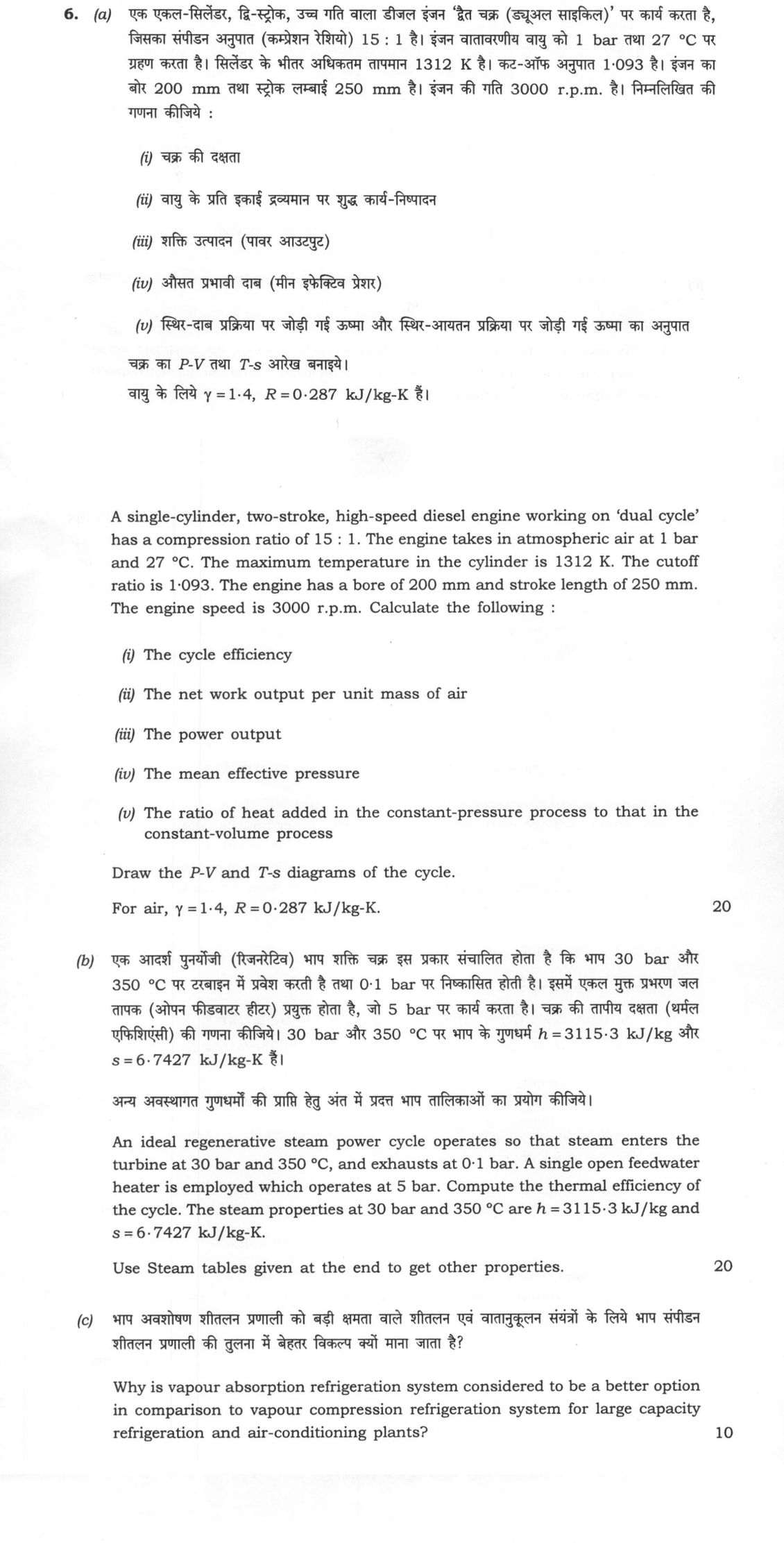
(a) A single-cylinder, two-stroke, high-speed diesel engine working on 'dual cycle' has a compression ratio of 15 : 1. The engine…
A single-cylinder, two-stroke, high-speed diesel engine working on 'dual cycle' has a compression ratio of 15 : 1. The engine takes in atmospheric air at 1 bar and 27 °C. The maximum temperature in the cylinder is 1312 K. The cutoff ratio is 1·093. The engine has a bore of 200 mm and stroke length of 250 mm. The engine speed is 3000 r.p.m. Calculate the following:
The cycle efficiency
The net work output per unit mass of air
The power output
The mean effective pressure
The ratio of heat added in the constant-pressure process to that in the constant-volume process
Draw the P-V and T-s diagrams of the cycle.
For air, γ = 1·4, R = 0·287 kJ/kg-K. 20 marks
An ideal regenerative steam power cycle operates so that steam enters the turbine at 30 bar and 350 °C, and exhausts at 0·1 bar. A single open feedwater heater is employed which operates at 5 bar. Compute the thermal efficiency of the cycle. The steam properties at 30 bar and 350 °C are h = 3115·3 kJ/kg and s = 6·7427 kJ/kg-K.
Use Steam tables given at the end to get other properties. 20 marks
Why is vapour absorption refrigeration system considered to be a better option in comparison to vapour compression refrigeration system for large capacity refrigeration and air-conditioning plants? 10 marks
हिंदी में प्रश्न पढ़ें
एक एकल-सिलेंडर, द्वि-स्ट्रोक, उच्च गति वाला डीजल इंजन 'हैट चक्र (ड्युअल साइकिल)' पर कार्य करता है, जिसका संपीडन अनुपात (कम्प्रेशन रेशियो) 15 : 1 है। इंजन वातावरणीय वायु को 1 bar तथा 27 °C पर प्रदान करता है। सिलेंडर के भीतर अधिकतम तापमान 1312 K है। कट-ऑफ अनुपात 1·093 है। इंजन का बोर 200 mm तथा स्ट्रोक लम्बाई 250 mm है। इंजन की गति 3000 r.p.m. है। निम्नलिखित की गणना कीजिये:
चक्र की दक्षता
वायु के प्रति इकाई द्रव्यमान पर शुद्ध कार्य-निष्पादन
शक्ति उत्पादन (पावर आउटपुट)
औसत प्रभावी दाब (मीन इफेक्टिव प्रेशर)
स्थिर-दाब प्रक्रिया पर जोड़ी गई ऊष्मा और स्थिर-आयतन प्रक्रिया पर जोड़ी गई ऊष्मा का अनुपात
चक्र का P-V तथा T-s आरेख बनाइये।
वायु के लिये γ = 1·4, R = 0·287 kJ/kg-K है। (20 अंक)
एक आदर्श पुनर्जीवी (रिजनरेटिव) भाप शक्ति चक्र इस प्रकार संचालित होता है कि भाप 30 bar और 350 °C पर टरबाइन में प्रवेश करती है तथा 0·1 bar पर निष्कासित होती है। इसमें एकल मुक्त प्रभरण जल तापक (ओपन फीडवाटर हीटर) प्रयुक्त होता है, जो 5 bar पर कार्य करता है। चक्र की तापीय दक्षता (थर्मल एफिशिएंसी) की गणना कीजिए। 30 bar और 350 °C पर भाप के गुणधर्म h = 3115·3 kJ/kg और s = 6·7427 kJ/kg-K हैं।
अन्य अवस्थागत गुणधर्मों की प्राप्ति हेतु अंत में प्रदत्त भाप तालिकाओं का प्रयोग कीजिए। (20 अंक)
भाप अवशोषण शीतलन प्रणाली को बड़ी क्षमता वाले शीतलन एवं वातानुकूलन संयंत्रों के लिए भाप संपीडन शीतलन प्रणाली की तुलना में बेहतर विकल्प क्यों माना जाता है? (10 अंक)
The figure this question refers to, in words
The question paper is a scan and the diagram did not survive as text. This is the figure as read from the original page — every component, value and label — so the question can be worked from the text below.
(b) Table: Steam Table [Saturated Water : Pressure] Columns: Pressure (kPa or MPa) | Temp. T (°C) | Specific Volume v_f (m^3/kg) | Specific Volume v_g (m^3/kg) | Internal Energy u_f (kJ/kg) | Internal Energy u_fg (kJ/kg) | Internal Energy u_g (kJ/kg) | Enthalpy h_f (kJ/kg) | Enthalpy h_fg (kJ/kg) | Enthalpy h_g (kJ/kg) | Entropy s_f (kJ/kg·K) | Entropy s_fg (kJ/kg·K) | Entropy s_g (kJ/kg·K) 0.6113 kPa | 0.01 | 0.001000 | 206.132 | 0 | 2375.3 | 2375.3 | 0.00 | 2501.3 | 2501.3 | 0 | 9.1562 | 9.1562 1.0 kPa | 6.98 | 0.001000 | 129.208 | 29.29 | 2355.7 | 2385.0 | 29.29 | 2484.9 | 2514.2 | 0.1059 | 8.8697 | 8.9756 1.5 kPa | 13.03 | 0.001001 | 87.980 | 54.70 | 2338.6 | 2393.3 | 54.70 | 2470.6 | 2525.3 | 0.1956 | 8.6322 | 8.8278 2.0 kPa | 17.50 | 0.001001 | 67.004 | 73.47 | 2326.0 | 2399.5 | 73.47 | 2460.0 | 2533.5 | 0.2607 | 8.4629 | 8.7236 2.5 kPa | 21.08 | 0.001002 | 54.254 | 88.47 | 2315.9 | 2404.4 | 88.47 | 2451.6 | 2540.0 | 0.3120 | 8.3311 | 8.6431 3.0 kPa | 24.08 | 0.001003 | 45.665 | 101.03 | 2307.5 | 2408.5 | 101.03 | 2444.5 | 2545.5 | 0.3545 | 8.2231 | 8.5775 4.0 kPa | 28.96 | 0.001004 | 34.800 | 121.44 | 2293.7 | 2415.2 | 121.44 | 2432.9 | 2554.4 | 0.4226 | 8.0520 | 8.4746 5.0 kPa | 32.88 | 0.001005 | 28.193 | 137.79 | 2282.7 | 2420.5 | 137.79 | 2423.7 | 2561.4 | 0.4763 | 7.9187 | 8.3950 7.5 kPa | 40.29 | 0.001008 | 19.238 | 168.76 | 2261.7 | 2430.5 | 168.77 | 2406.0 | 2574.8 | 0.5763 | 7.6751 | 8.2514 10.0 kPa | 45.81 | 0.001010 | 14.674 | 191.79 | 2246.1 | 2437.9 | 191.81 | 2392.8 | 2584.6 | 0.6492 | 7.5010 | 8.1501 15.0 kPa | 53.97 | 0.001014 | 10.022 | 225.90 | 2222.8 | 2448.7 | 225.91 | 2373.1 | 2599.1 | 0.7548 | 7.2536 | 8.0084 20.0 kPa | 60.06 | 0.001017 | 7.649 | 251.35 | 2205.4 | 2456.7 | 251.38 | 2358.3 | 2609.7 | 0.8319 | 7.0766 | 7.9085 25.0 kPa | 64.97 | 0.001020 | 6.204 | 271.88 | 2191.2 | 2463.1 | 271.90 | 2346.3 | 2618.2 | 0.8930 | 6.9383 | 7.8313 30.0 kPa | 69.10 | 0.001022 | 5.229 | 289.18 | 2179.2 | 2468.4 | 289.21 | 2336.1 | 2625.3 | 0.9439 | 6.8247 | 7.7686 40.0 kPa | 75.87 | 0.001026 | 3.993 | 317.51 | 2159.5 | 2477.0 | 317.55 | 2319.2 | 2636.7 | 1.0258 | 6.6441 | 7.6700 50.0 kPa | 81.33 | 0.001030 | 3.240 | 340.42 | 2143.4 | 2483.8 | 340.47 | 2305.4 | 2645.9 | 1.0910 | 6.5029 | 7.5939 75.0 kPa | 91.77 | 0.001037 | 2.217 | 384.29 | 2112.4 | 2496.7 | 384.36 | 2278.6 | 2663.0 | 1.2129 | 6.2434 | 7.4563 0.100 MPa | 99.62 | 0.001043 | 1.6940 | 417.33 | 2088.7 | 2506.1 | 417.44 | 2258.0 | 2675.5 | 1.3025 | 6.0568 | 7.3593 0.125 MPa | 105.99 | 0.001048 | 1.3749 | 444.16 | 2069.3 | 2513.5 | 444.30 | 2241.1 | 2685.3 | 1.3739 | 5.9104 | 7.2843 0.150 MPa | 111.37 | 0.001053 | 1.1593 | 466.92 | 2052.7 | 2519.6 | 467.08 | 2226.5 | 2693.5 | 1.4335 | 5.7897 | 7.2232 0.175 MPa | 116.06 | 0.001057 | 1.0036 | 486.78 | 2038.1 | 2524.9 | 486.97 | 2213.6 | 2700.5 | 1.4848 | 5.6868 | 7.1717 0.200 MPa | 120.23 | 0.001061 | 0.8857 | 504.47 | 2025.0 | 2529.5 | 504.68 | 2202.0 | 2706.6 | 1.5300 | 5.5970 | 7.1271 0.225 MPa | 124.00 | 0.001064 | 0.7933 | 520.45 | 2013.1 | 2533.6 | 520.69 | 2191.3 | 2712.0 | 1.5705 | 5.5173 | 7.0878 0.250 MPa | 127.43 | 0.001067 | 0.7187 | 535.08 | 2002.1 | 2537.2 | 535.34 | 2181.5 | 2716.9 | 1.6072 | 5.4455 | 7.0526
Model answer
Written by UPSC Answer Check against this question's marking rubric, to the expected length. UPSC does not publish answers for Mains — this is one way to score well, not an official key.
(a)(i) Air-standard dual-cycle analysis. Given: r = 15, ρ = 1.093, T₁ = 27 °C = 300 K, T₄ = 1312 K, γ = 1.4, R = 0.287 kJ/kg-K. Isentropic compression 1–2: T₂ = T₁ r^(γ−1) = 300 × 15^0.4 = 886.25 K. Constant-pressure process 3–4: ρ = V₄/V₃ = T₄/T₃, so T₃ = 1312/1.093 = 1200.37 K. Isentropic expansion 4–5: T₅ = T₄(ρ/r)^(γ−1) = 1312 × (1.093/15)^0.4 = 460.20 K. cv = R/(γ−1) = 0.287/0.4 = 0.7175 kJ/kg-K, cp = γcv = 1.0045 kJ/kg-K. qin = cv(T₃−T₂) + cp(T₄−T₃) qin = 0.7175(314.11) + 1.0045(111.63) = 225.38 + 112.14 = 337.51 kJ/kg. qout = cv(T₅−T₁) = 0.7175(160.20) = 114.94 kJ/kg. η = 1 − qout/qin = 1 − 114.94/337.51. η = 0.6594 = 65.94 %.
(a)(ii) Net work per unit mass: wnet = qin − qout = 337.51 − 114.94. wnet = 222.57 kJ/kg.
(a)(iii) Swept volume: Vs = (π/4)D²L = (π/4)(0.2)²(0.25) = 0.007854 m³. V₁ = Vs r/(r−1) = 0.007854 × 15/14 = 0.008415 m³. Mass per cycle: m = P₁V₁/(RT₁) = 100 × 0.008415/(0.287 × 300) = 0.009773 kg. For a two-stroke engine, cycles/s = N/60 = 3000/60 = 50. Power = m wnet × cycles/s = 0.009773 × 222.57 × 50. Power = 108.76 kW.
(a)(iv) Mean effective pressure: MEP = wnet per cycle / Vs = (0.009773 × 222.57)/0.007854 = 276.97 kPa. MEP = 276.97 kPa = 2.77 bar.
(a)(v) Ratio of constant-pressure heat to constant-volume heat: Qp/Qv = cp(T₄−T₃)/[cv(T₃−T₂)] = 1.0045 × 111.63/(0.7175 × 314.11). Qp/Qv = 0.4976.
Diagrams: P-V: 1→2 isentropic compression, 2→3 constant-volume heat addition, 3→4 constant-pressure heat addition, 4→5 isentropic expansion, 5→1 constant-volume heat rejection. T-s: 1→2 vertical isentropic compression, 2→3 constant-volume heat addition (steeper up-right), 3→4 constant-pressure heat addition (less steep up-right), 4→5 vertical isentropic expansion, 5→1 constant-volume heat rejection (down-left).
(b) Ideal regenerative Rankine cycle with one open feedwater heater at 5 bar. At 5 bar (0.5 MPa), from steam tables: h_f = 640.23 kJ/kg, h_fg = 2108.5 kJ/kg, s_f = 1.8607 kJ/kg-K, s_fg = 4.9606 kJ/kg-K, v_f = 0.001093 m³/kg. At 0.1 bar (10 kPa): h_f = 191.81 kJ/kg, h_fg = 2392.8 kJ/kg, s_f = 0.6492 kJ/kg-K, s_fg = 7.5010 kJ/kg-K, v_f = 0.001010 m³/kg. State 1: h₁ = 3115.3 kJ/kg, s₁ = 6.7427 kJ/kg-K. At 5 bar: x₂ = (6.7427 − 1.8607)/4.9606 = 0.9842. h₂ = 640.23 + 0.9842 × 2108.5 = 2715.3 kJ/kg. At 0.1 bar: x₃ = (6.7427 − 0.6492)/7.5010 = 0.8124. h₃ = 191.81 + 0.8124 × 2392.8 = 2135.6 kJ/kg. Condensate pump to heater: h₅ = h₄ + v₄(P₅ − P₀.₁) = 191.81 + 0.001010(500 − 10) = 192.30 kJ/kg. Open FWH energy balance: yh₂ + (1−y)h₅ = h₆ = h_f at 5 bar = 640.23 kJ/kg. y = (640.23 − 192.30)/(2715.3 − 192.30) = 0.1775. Feed pump to boiler: h₇ = h₆ + v₆(3000 − 500) = 640.23 + 0.001093 × 2500 = 642.96 kJ/kg. qin = h₁ − h₇ = 3115.3 − 642.96 = 2472.34 kJ/kg. Turbine work: wT = (h₁ − h₂) + (1−y)(h₂ − h₃) = 399.98 + 0.8225 × 579.70 = 876.76 kJ/kg. Pump work: wP = (1−y)(h₅ − h₄) + (h₇ − h₆) = 0.407 + 2.733 = 3.14 kJ/kg. η = (wT − wP)/qin = (876.76 − 3.14)/2472.34. η = 0.3534 = 35.34 %.
(c) Vapour absorption refrigeration is preferred for large-capacity plants because:
- It uses low-grade heat, such as waste heat, solar heat, turbine exhaust, or process heat, instead of costly high-grade mechanical work.
- It has very few moving parts; the compressor is replaced by a pump, giving less noise, vibration, wear, and maintenance.
- It is reliable and long-lasting, which is important in large continuous air-conditioning and refrigeration plants.
- The refrigerants used, such as water–LiBr or ammonia–water, are relatively cheap and environment-friendly; water–LiBr has no ozone-depletion or global-warming problem.
- It reduces electrical peak demand and operating cost where waste heat is available.
- It scales well for large capacities, where the size and power consumption of a vapour-compression compressor become very high. Limitation: its COP is usually lower than vapour compression, and it needs a heat source and cooling water, so it is best where cheap heat is available.
What "Calculate" is asking you to do
Apply the standard formula or schedule to data the question has already supplied — a table of readings, cost records, a balance sheet — and produce the number. The method is rarely in doubt; the marks sit in the named intermediate quantities, each of which has to appear as a labelled line.
Structure that answers it
Data as given → formula or standard treatment, named → substitution → each intermediate, labelled → result with units
Where marks are lost
Omitting an intermediate the marking scheme pays for separately, or rounding at an intermediate line so the final figure drifts. In commerce and accountancy, any figure in a statement that no numbered working note supports is treated as unearned.
How this answer will be evaluated
Approach
Framework: Mechanical Engineering, Paper 2. (a) calculate: given > formula > substitution > result with units > interpretation | (b) calculate: given > formula > substitution > result with units > interpretation | (c) justify: claim > 3-4 reasons > evidence > conclusion Full marks: Rigorous application of thermodynamic laws with clear diagrams and physical interpretation.
Key points expected
- State given data and assumptions (γ, R, T1, P1)
- Calculate intermediate state temperatures (T2, T3, T4)
- Apply dual cycle efficiency formula with correct ratios
- Calculate power output using engine speed and displacement
- Identify state points and extract properties from steam tables
- Calculate mass fraction of steam bled for the heater
- Compute turbine work and pump work for each stage
- Apply thermal efficiency formula (Net Work / Heat Input)
Evaluation rubric
Each sub-part is marked on its own, against the marks and word limit printed on the paper.
- (a) Compute cycle efficiency, work, power, MEP, and heat ratio for a dual cycle engine. 20 marks
calculate— given → formula → substitution → result with units → interpretation
Must cover
- State given data and assumptions (γ, R, T1, P1)
- Calculate intermediate state temperatures (T2, T3, T4)
- Apply dual cycle efficiency formula with correct ratios
- Calculate power output using engine speed and displacement
Loses marks
- Plugging numbers without stating governing equations
- Omitting units in intermediate or final calculations
- Using incorrect state points for the dual cycle
Earns more
- Draw labelled P-V and T-s diagrams
- Show step-by-step substitution for each sub-part
- Verify dimensional consistency of work and power
- Explicitly state the cutoff and pressure ratios used
Extra mark
- Provide a physical interpretation of the efficiency value
- Compare the calculated MEP with typical engine values
- (b) Determine thermal efficiency of an ideal regenerative steam power cycle. 20 marks
calculate— given → formula → substitution → result with units → interpretation
Must cover
- Identify state points and extract properties from steam tables
- Calculate mass fraction of steam bled for the heater
- Compute turbine work and pump work for each stage
- Apply thermal efficiency formula (Net Work / Heat Input)
Loses marks
- Incorrect extraction of properties from steam tables
- Neglecting the pump work in the net work calculation
- Failing to account for the mass flow split at the heater
Earns more
- Draw a schematic of the regenerative cycle
- Show the energy balance for the open feedwater heater
- Clearly label enthalpy values at each state point
- State the assumption of isentropic turbine and pump processes
Extra mark
- Discuss the impact of regeneration on cycle efficiency
- Provide a T-s diagram with the cycle path marked
- (c) Explain why vapour absorption is preferred for large capacity plants. 10 marks
justify— claim → 3-4 reasons → evidence → conclusion
Must cover
- Identify the primary energy source for absorption systems
- Contrast the mechanical drive of compression systems
- Highlight the advantage of using waste heat or solar energy
- Mention the reduction in moving parts and maintenance
Loses marks
- Confusing the working fluids of the two systems
- Failing to link the 'large capacity' aspect to the justification
- Providing a generic comparison without specific advantages
Earns more
- Discuss the environmental benefit of using non-electric power
- Compare the noise levels of the two systems
- Reference specific applications like industrial waste heat recovery
- Mention the stability of the absorption process for large loads
Extra mark
- Provide a specific example of a large-scale absorption plant
- Quantify the potential energy savings in a comparative scenario
Practice this exact question
Write your answer and it is marked point by point against the model answer above — what you covered, what you missed, what you got wrong.
Evaluate my answer →More from Mechanical Engineering 2025 Paper II
- Q3 (a) A long cylindrical rod of radius 10 cm consists of a nuclear reacting material (k = 0…
- Q4 (a) A shell and tube type condenser is employed in a steam power plant to handle 35000 kg…
- Q5 (a) With the help of P-θ (pressure-crank angle) diagram, compare the knock in SI and CI e…
- Q6 (a) A single-cylinder, two-stroke, high-speed diesel engine working on 'dual cycle' has a…
- Q7 (a) A two-stage turbine receives steam at 50 bar and 350 °C. At 1·5 bar, the high-pressur…
- Q8 (a) The following data refers to a single-stage vapour compression refrigeration system :…