Paper II — Q8
(a) The figure shows an overflow spillway which is 40 m high. At the design energy head of 2·5 m over the spillway…
The figure shows an overflow spillway which is 40 m high. At the design energy head of 2·5 m over the spillway, determine— the sequent depths;
the energy loss;
the percentage of initial energy lost for the hydraulic jump formed on a horizontal apron at the toe of the spillway. 20 marks
20 MLD of water with 80 mg/L of suspended solids is treated with alum [Al₂(SO₄)₃ · 14·3H₂O] dose of 60 mg/L. Find the quantity of sludge produced assuming that sufficient natural alkalinity is available. Take specific gravity of sludge as 1·04 and removal efficiency as 60%. 15 marks
Explaining the procedure for developing a wind rose, discuss the applications of wind rose using a typical sketch. 15 marks
हिंदी में प्रश्न पढ़ें
चित्र में एक अधिप्रवाही उत्प्लाव दर्शाया गया है, जो 40 m ऊँचा है। उत्प्लाव के ऊपर 2·5 m की अभिकल्पन ऊर्जा दाबोच्चता एवं क्षैतिज अंचल (एप्रन) पर उत्प्लाव के पदार पर बने जलोच्छल के लिए निम्नलिखित को निर्धारित कीजिए :
अनुक्रम गहराइयाँ
ऊर्जा ह्रास
ह्रास हुई प्रारंभिक ऊर्जा का प्रतिशत
20 अंक
20 MLD जल, जिसमें 80 mg/L निलम्बित ठोस पदार्थ है, को फिटकरी [Al₂(SO₄)₃ · 14·3H₂O] की 60 mg/L की खुराक के साथ उपचारित किया जाता है। यह मानते हुए कि पर्याप्त प्राकृतिक क्षारीयता उपलब्ध है, उत्पन्न अवपेक की मात्रा को ज्ञात कीजिए। अवपेक के विशिष्ट घनत्व को 1·04 और पृथक्कीकरण दक्षता को 60% लीजिए। 15 अंक
एक विंड रोज को विकसित करने की प्रक्रिया को समझाते हुए एक विशिष्ट रेखाचित्र का उपयोग करके विंड रोज के अनुप्रयोगों की चर्चा कीजिए। 15 अंक
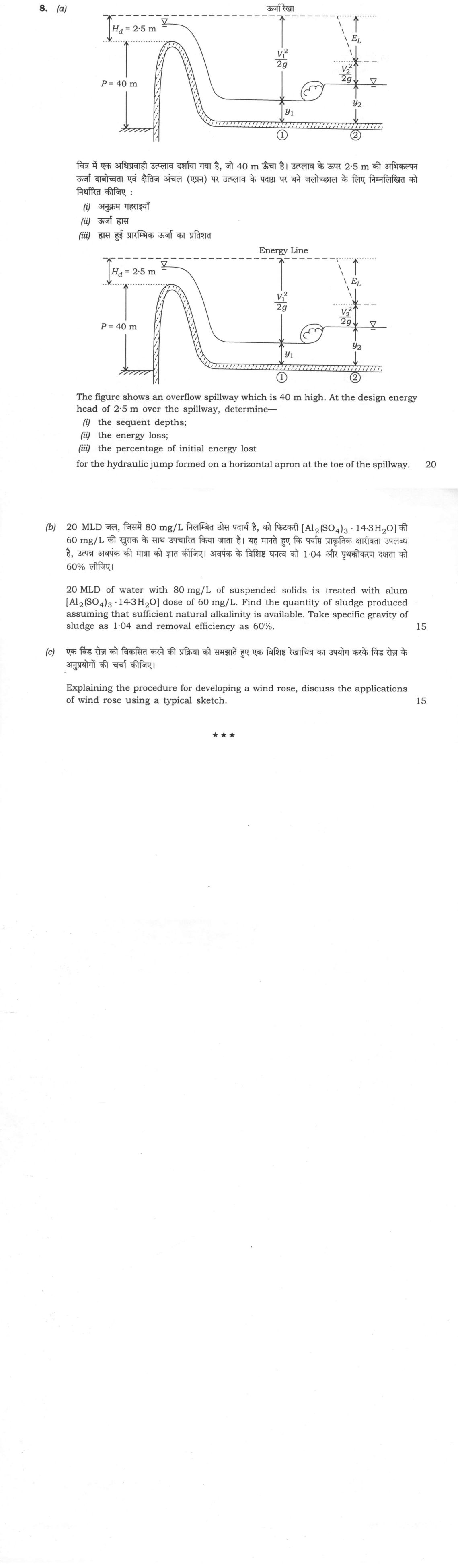
The figure this question refers to, in words
The question paper is a scan and the diagram did not survive as text. This is the figure as read from the original page — every component, value and label — so the question can be worked from the text below.
(a) A schematic diagram showing an overflow spillway with a hydraulic jump formed on a horizontal apron at the toe. Key dimensions and parameters shown are: spillway height P = 40 m from the upstream bed to the spillway crest; design energy head over the spillway crest H_d = 2.5 m, measured vertically from the crest to a horizontal dashed line labelled 'Energy Line'. Water flows over the crest down the curved face to a horizontal apron. At section (1) before the jump, the water depth is marked as y_1, and the velocity head V_1^2 / (2g) extends from the water surface up to the Energy Line. A hydraulic jump occurs between section (1) and section (2). At section (2) downstream of the jump, the depth is y_2, the velocity head is V_2^2 / (2g), and the energy loss across the jump is indicated by a vertical dimension labelled E_L between the upstream Energy Line and the downstream total energy level.
Model answer
Written by UPSC Answer Check against this question's marking rubric, to the expected length. UPSC does not publish answers for Mains — this is one way to score well, not an official key.
(a) Use the ogee spillway discharge equation: q = C H_d^(3/2). For a standard ogee profile at design head, C = 2.2 m^(1/2)/s. H_d = 2.5 m, so q = 2.2 × 2.5^(3/2) = 8.696 m³/s per m width.
Total energy at the toe above the apron, neglecting spillway friction, is E₁ = P + H_d = 40 + 2.5 = 42.5 m. At section (1), specific energy is E₁ = y₁ + V₁²/(2g) = y₁ + q²/(2g y₁²). Thus, y₁ + 8.696²/(2 × 9.81 × y₁²) = 42.5. Solving this cubic by iteration: y₁ ≈ 0.302 m.
Froude number: F₁² = q²/(g y₁³) = 8.696²/(9.81 × 0.302³) = 279.4, so F₁ ≈ 16.7.
Using the Belanger momentum equation for a rectangular horizontal apron: y₂ = (y₁/2)(√(1 + 8F₁²) − 1) = (0.302/2)(√(1 + 8 × 279.4) − 1) = 6.99 m.
(i) Sequent depths: y₁ = 0.302 m, y₂ = 6.99 m.
(ii) Energy loss in the jump: ΔE = (y₂ − y₁)³/(4 y₁ y₂) = (6.99 − 0.302)³/(4 × 0.302 × 6.99) = 35.4 m.
Energy loss = 35.4 m.
(iii) Initial energy at section (1) is E₁ = 42.5 m. Percentage of initial energy lost = (ΔE/E₁) × 100 = (35.4/42.5) × 100 = 83.3%.
Percentage lost = 83.3%.
(b) Flow Q = 20 MLD = 20 × 10⁶ L/d. Alum dose = 60 mg/L, so mass of alum = 60 × 20 × 10⁶ = 1.200 × 10⁹ mg/d = 1200 kg/d.
The reaction with natural alkalinity is: Al₂(SO₄)₃·14.3H₂O + 3Ca(HCO₃)₂ → 2Al(OH)₃↓ + 3CaSO₄ + 6CO₂ + 14.3H₂O.
Molecular weights: M(Al₂(SO₄)₃·14.3H₂O) = 2×27 + 3×(32+4×16) + 14.3×18 = 599.4 g/mol. M(Al(OH)₃) = 27 + 3×(16+1) = 78 g/mol.
Al(OH)₃ produced = 1200 × (2×78/599.4) = 312.3 kg/d.
Suspended solids removed = 80 × 0.60 = 48 mg/L. Mass of removed SS = 48 × 20 × 10⁶ mg/d = 960 kg/d.
Total dry sludge = 312.3 + 960 = 1272.3 kg/d.
Specific gravity of sludge = 1.04, so density = 1040 kg/m³. Volume of sludge = 1272.3/1040 = 1.22 m³/d.
Sludge produced ≈ 1272 kg/d dry solids, equivalent to 1.22 m³/d.
(c) A wind rose is a polar diagram showing the frequency of wind from each compass direction, usually with speed classes.
Procedure:
- Collect continuous wind records for a chosen period, noting direction to 16 compass points and speed.
- Tabulate frequency of occurrence for each direction and speed class, e.g., calm, 0–5, 5–10, 10–15 km/h.
- Convert frequencies to percentages of total observations and compute the calm percentage.
- Draw radial axes for N, NNE, NE, … and concentric circles giving frequency scale, e.g., 5%, 10%, 15%.
- On each direction, draw a sector whose radial length equals the total percentage frequency from that direction.
- Divide each sector into speed bands and shade them distinctly. Put the calm percentage at the centre.
- Optionally plot the resultant wind vector.
Typical sketch: a circle with N at the top and 16 radial arms. The longest arm, say towards NW, shows the prevailing wind. Each arm is stacked with speed bands such as 0–5, 5–10, >10 km/h. Concentric rings are marked 5%, 10%, 15%; the centre shows calm, e.g., 8%.
Applications:
- Air pollution control: siting industries, residential areas and stacks; assessing downwind pollution impact.
- Urban and building planning: natural ventilation, building orientation, windbreaks and thermal comfort.
- Agriculture: shelterbelts, spraying, pesticide drift and evaporation studies.
- Aviation and wind energy: runway orientation, wind turbine siting and wind-power assessment.
- Marine and climate studies: wave and current prediction, port layout, monsoon and seasonal wind analysis.
What "Solve" is asking you to do
Choose the method, then carry it through to a final answer. Identifying what kind of problem this is and why that method applies is the first thing marked; a correct figure arrived at invisibly earns almost nothing.
Structure that answers it
Given data and what is required → method chosen, with the reason it applies → set-up (equation, circuit, free body, trial balance) → working, step by step → answer with units and any condition of validity
Where marks are lost
Doing the middle steps mentally and writing only the result. In mathematics papers, a further loss comes from giving a decimal where the exact value in surds or fractions was wanted, or from skipping the justification a part explicitly asks for.
How this answer will be evaluated
Approach
(a) calculate: given > formula > substitution > result with units > interpretation | (b) calculate: given > formula > substitution > result with units > interpretation | (c) discuss: intro > 3-4 dimensions > example > balanced close Full marks: Complete calculations with correct formulas, clear sketches, and proper engineering context for all parts.
Key points expected
- Calculate approach velocity V1 using energy head
- Apply conjugate depth relation for sequent depths
- Compute energy loss using depth difference formula
- Calculate percentage of initial energy lost
- Calculate alum consumption and resulting sludge mass
- Apply 60% removal efficiency to suspended solids
- Use specific gravity 1.04 for volume calculation
- Account for chemical sludge from alum reaction
Evaluation rubric
Each sub-part is marked on its own, against the marks and word limit printed on the paper.
- (a) Determine sequent depths, energy loss, and percentage energy loss for the hydraulic jump. 20 marks
calculate— given → formula → substitution → result with units → interpretation
Must cover
- Calculate approach velocity V1 using energy head
- Apply conjugate depth relation for sequent depths
- Compute energy loss using depth difference formula
- Calculate percentage of initial energy lost
Loses marks
- Omitting velocity head in energy calculation
- Incorrect application of conjugate depth formula
- Missing percentage calculation or wrong denominator
Earns more
- Correct application of specific energy concept
- Clear identification of pre-jump and post-jump depths
- Proper unit conversion and dimensional consistency
- Sketch showing hydraulic jump location
Extra mark
- Reference to IS 6934 for spillway design
- Discussion of jump stability criteria
- (b) Find quantity of sludge produced from alum treatment of 20 MLD water. 15 marks
calculate— given → formula → substitution → result with units → interpretation
Must cover
- Calculate alum consumption and resulting sludge mass
- Apply 60% removal efficiency to suspended solids
- Use specific gravity 1.04 for volume calculation
- Account for chemical sludge from alum reaction
Loses marks
- Ignoring chemical sludge from alum
- Wrong application of removal efficiency
- Omitting specific gravity in volume conversion
Earns more
- Correct stoichiometry for alum-hydroxide reaction
- Separate calculation for organic and chemical sludge
- Clear statement of assumptions about alkalinity
- Final answer in appropriate units (m³/day)
Extra mark
- Mention of sludge characteristics (pH, density)
- Reference to standard sludge yield factors
- (c) Explain wind rose development procedure and discuss its applications. 15 marks
discuss— intro → 3-4 dimensions → example → balanced close
Must cover
- Describe data collection and wind direction frequency
- Explain construction of wind rose diagram
- Identify at least 3 applications in engineering
- Provide typical sketch of wind rose
Loses marks
- Missing sketch or diagram of wind rose
- Vague description of construction procedure
- Applications not specific to civil engineering
Earns more
- Mention of wind speed distribution in rose
- Application to building orientation and ventilation
- Use in industrial siting and pollution dispersion
- Reference to meteorological data sources
Extra mark
- Example of wind rose for specific location
- Discussion of seasonal variations in wind patterns
Practice this exact question
Write your answer and it is marked point by point against the model answer above — what you covered, what you missed, what you got wrong.
Evaluate my answer →More from Civil Engineering 2025 Paper II
- Q5 (a) A box culvert has an expected life of 10 years. (i) If the acceptable risk of at leas…
- Q6 (a) A storm over a catchment of area 5 km² had a duration of 14 hours. The mass curve of…
- Q7 (a) The data related to the activated sludge process is given below: Population = 500000…
- Q8 (a) The figure shows an overflow spillway which is 40 m high. At the design energy head o…