Paper I — Q1
(a) A frictionless pulley A as shown in the figure is supported by two bars AB and AC which are hinged at B and C to a vertical…
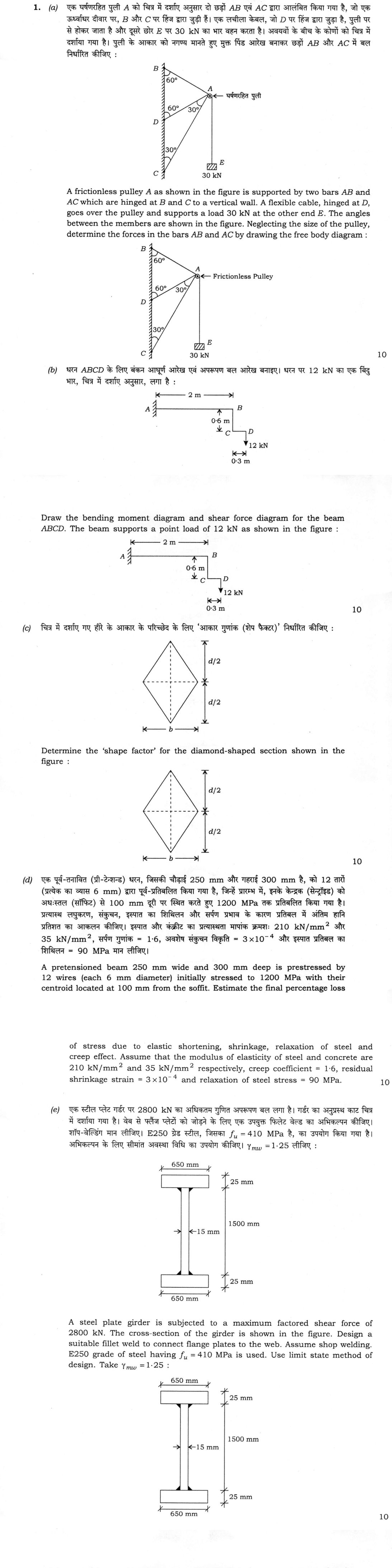
A frictionless pulley A as shown in the figure is supported by two bars AB and AC which are hinged at B and C to a vertical wall. A flexible cable, hinged at D, goes over the pulley and supports a load 30 kN at the other end E. The angles between the members are shown in the figure. Neglecting the size of the pulley, determine the forces in the bars AB and AC by drawing the free body diagram : 10 marks
Draw the bending moment diagram and shear force diagram for the beam ABCD. The beam supports a point load of 12 kN as shown in the figure : 10 marks
Determine the 'shape factor' for the diamond-shaped section shown in the figure : 10 marks
A pretensioned beam 250 mm wide and 300 mm deep is prestressed by 12 wires (each 6 mm diameter) initially stressed to 1200 MPa with their centroid located at 100 mm from the soffit. Estimate the final percentage loss of stress due to elastic shortening, shrinkage, relaxation of steel and creep effect. Assume that the modulus of elasticity of steel and concrete are 210 kN/mm² and 35 kN/mm² respectively, creep coefficient = 1·6, residual shrinkage strain = 3×10⁻⁴ and relaxation of steel stress = 90 MPa. 10 marks
A steel plate girder is subjected to a maximum factored shear force of 2800 kN. The cross-section of the girder is shown in the figure. Design a suitable fillet weld to connect flange plates to the web. Assume shop welding. E250 grade of steel having f_u = 410 MPa is used. Use limit state method of design. Take γ_mw = 1·25 : 10 marks
हिंदी में प्रश्न पढ़ें
एक घर्षणहित पुली A को चित्र में दर्शाए अनुसार दो छड़ों AB एवं AC द्वारा आलंबित किया गया है, जो एक ऊर्ध्वाधर दीवार पर, B और C पर हिंज द्वारा जुड़ी है। एक लचीली केबल, जो D पर हिंज द्वारा जुड़ा है, पुली पर से होकर जाता है और दूसरे छोर E पर 30 kN का भार वहन करता है। अवयवों के बीच के कोणों को चित्र में दर्शाया गया है। पुली के आकार को नगण्य मानते हुए मुक्त पिंड आरेख बनाकर छड़ों AB और AC में बल निर्धारित कीजिए : (10 अंक)
धरन ABCD के लिए बंकन आघूर्ण आरेख एवं अपरूपण बल आरेख बनाइए। धरन पर 12 kN का एक बिंदु भार, चित्र में दर्शाए अनुसार, लगा है : (10 अंक)
चित्र में दर्शाए गए हीरे के आकार के परिच्छेद के लिए 'आकार गुणांक (शेप फैक्टर)' निर्धारित कीजिए : (10 अंक)
एक पूर्व-तनावित (प्री-टेशन्ड) धरन, जिसकी चौड़ाई 250 mm और गहराई 300 mm है, को 12 तारों (प्रत्येक का व्यास 6 mm) द्वारा पूर्व-प्रतिबलित किया गया है, जिन्हें प्रारंभ में, इनके केन्द्रक (सेंट्रॉइड) को अधःस्तल (सॉफिट) से 100 mm दूरी पर स्थित करते हुए 1200 MPa तक प्रतिबलित किया गया है। प्रत्यास्थ लघुकरण, संकुचन, इस्पात का शिथिलन और सर्पण प्रभाव के कारण प्रतिबल में अंतिम हानि प्रतिशत का आकलन कीजिए। इस्पात और कंक्रीट का प्रत्यास्थता मापांक क्रमशः 210 kN/mm² और 35 kN/mm², सर्पण गुणांक = 1.6, अवशेष संकुचन विकृति = 3×10⁻⁴ और इस्पात प्रतिबल का शिथिलन = 90 MPa मान लीजिए। (10 अंक)
एक स्टील प्लेट गर्डर पर 2800 kN का अधिकतम गुणित अपरूपण बल लगा है। गर्डर का अनुप्रस्थ काट चित्र में दर्शाया गया है। वेब से प्लेंज प्लेटों को जोड़ने के लिए एक उपयुक्त फिलेट वेल्ड का अभिकल्पन कीजिए। शॉप-वेल्डिंग मान लीजिए। E250 ग्रेड स्टील, जिसका f_u = 410 MPa है, का उपयोग किया गया है। अभिकल्पन के लिए सीमांत अवस्था विधि का उपयोग कीजिए। γ_mw = 1·25 लीजिए : (10 अंक)
Model answer
Drafted with AI by UPSC Answer Check against this question's marking rubric, to the expected length. UPSC does not publish answers for Mains — this is one way to score well, not an official key. How we build rubrics and answers.
(a) Forces in bars AB and AC (10 marks)
Take the pulley at A as the free body. The frictionless pulley passes the cable round without changing its tension, so the cable pulls on it with T = 30 kN in both segments, one along AE (vertically downward) and one along AD (towards D). The geometry from the figure gives AB at 30° above the horizontal (towards B), AD at 30° below the horizontal (towards D) and AC at 60° below the horizontal (towards C). Assume both bar forces to be tensile (pulling on A towards B and C).

Cable forces on A: AD segment 30(-cos 30°, -sin 30°) = (-25.98, -15.0) kN, and AE segment (0, -30) kN.
ΣFx = 0: -25.98 - 0.866 F_AB - 0.5 F_AC = 0
ΣFy = 0: -15 - 30 + 0.5 F_AB - 0.866 F_AC = 0
The second equation gives F_AB = 90 + 1.732 F_AC. Substituting into the first, -25.98 - 0.866(90 + 1.732 F_AC) - 0.5 F_AC = 0, so -25.98 - 77.94 - 1.5 F_AC - 0.5 F_AC = 0, and F_AC = -51.96 kN. Then F_AB = 90 - 90 = 0.
Result: F_AC = 51.96 kN (30√3), compression, and F_AB = 0. The resultant of the two cable pulls, 51.96 kN, acts exactly along the line AC towards C, so bar AC alone resists it, and AB is a zero-force member.
(b) Bent cantilever ABCD (10 marks)
Members: AB horizontal 2 m (fixed at A), BC vertical 0.6 m, CD horizontal 0.3 m to the right, with the 12 kN load acting downward at D. The load is 2 + 0.3 = 2.3 m to the right of A.
Reactions at A: H_A = 0, V_A = 12 kN upward, and M_A = 12 × 2.3 = 27.6 kN·m (hogging, tension on the top of AB).
Shear force (kN): CD 12 (constant); BC 0 (the shear in a vertical member is the horizontal force, which is nil); AB 12 (constant). Axial force: BC carries 12 kN in tension; AB and CD carry none.
Bending moment (kN·m, hogging), from the free end: at D, 0; along CD it increases linearly to 12 × 0.3 = 3.6 at C; along BC it is constant at 3.6 (no horizontal force); along AB it increases linearly from 3.6 at B to 3.6 + 12 × 2 = 27.6 at A. The maximum is 27.6 kN·m at the support.

(c) Shape factor of a diamond section (10 marks)
The section is two triangles of base b and height d/2, joined at the mid-depth, with total area A = bd/2.
Elastic section modulus. The neutral axis passes through the centre, at half-depth. Each triangle has a moment of inertia about its base of b(d/2)³/12 = bd³/96, so
I = 2 × bd³/96 = bd³/48, and y_max = d/2, so Z = I/y_max = (bd³/48)/(d/2) = bd²/24.
Plastic section modulus. The plastic neutral axis divides the area into two equal halves; by symmetry it is also the horizontal centre line. Each half is a triangle of area A/2 = bd/4 whose centroid is (d/2)/3 = d/6 from the axis. So
Z_p = (A/2)(ȳ₁ + ȳ₂) = (bd/4)(d/6 + d/6) = bd²/12.
Shape factor S = Z_p/Z = (bd²/12)/(bd²/24) = 2.0.
(d) Loss of prestress in a pretensioned beam (10 marks)
Data: b = 250 mm, D = 300 mm; 12 wires of 6 mm diameter; initial stress 1200 MPa; wire centroid 100 mm above the soffit; E_s = 210 kN/mm², E_c = 35 kN/mm²; creep coefficient 1.6; residual shrinkage strain 3 × 10⁻⁴; relaxation 90 MPa.
Steel area A_p = 12 × π(6)²/4 = 339.3 mm². Initial force P = 1200 × 339.3 = 407.15 kN.
Section: A = 250 × 300 = 75 000 mm², I = 250 × 300³/12 = 5.625 × 10⁸ mm⁴, and the eccentricity e = 150 - 100 = 50 mm. Modular ratio m = 210/35 = 6.
Concrete stress at the level of the steel: f_c = P/A + Pe²/I = 407 150/75 000 + 407 150 × 50²/5.625 × 10⁸ = 5.43 + 1.81 = 7.24 N/mm² (self-weight neglected).
- Elastic shortening: m f_c = 6 × 7.24 = 43.4 MPa.
- Shrinkage: ε_sh E_s = 3 × 10⁻⁴ × 210 000 = 63.0 MPa.
- Creep: φ m f_c = 1.6 × 6 × 7.24 = 69.5 MPa.
- Relaxation of steel: 90 MPa (given).
Total loss = 43.4 + 63.0 + 69.5 + 90 = 265.9 MPa, which is 265.9/1200 = 22.2% of the initial stress. The effective prestress is about 934 MPa.
(e) Fillet weld of the flange to the web of a plate girder (10 marks)
Section: web 1500 × 15 mm, flanges 650 × 25 mm, factored shear V = 2800 kN.
Moment of inertia. Web: 15 × 1500³/12 = 4.219 × 10⁹ mm⁴. Each flange: area 650 × 25 = 16 250 mm², centroid 750 + 12.5 = 762.5 mm from the axis, so its contribution is 16 250 × 762.5² + 650 × 25³/12 = 9.448 × 10⁹ + 0.0008 × 10⁹ mm⁴. Total I = 4.219 × 10⁹ + 2 × 9.449 × 10⁹ = 2.312 × 10¹⁰ mm⁴.
First moment of one flange about the axis: Q = 16 250 × 762.5 = 1.239 × 10⁷ mm³.
Horizontal shear flow at the flange-web junction: q = VQ/I = 2800 × 10³ × 1.239 × 10⁷ / 2.312 × 10¹⁰ = 1501 N/mm (about 1.50 kN/mm).
Two fillet welds (one on each side of the web) share this, so the force per weld is 1501/2 = 750 N/mm.
Design strength of a fillet weld per unit length (IS 800:2007): P_w = 0.7 s f_u/(√3 γ_mw) = 0.7 s × 410/(1.732 × 1.25) = 132.6 s N/mm, with s the weld size in mm.
Required size: s = 750/132.6 = 5.66 mm.
Limits from IS 800 Table 21 and the maximum size rule: the thicker part joined is the 25 mm flange, so the minimum size is 6 mm (thickness 20-32 mm); the maximum is the thickness of the thinner part, 15 mm.
Provide a 6 mm continuous fillet weld on both sides of the web, shop welded. It satisfies the minimum (6 mm), the maximum (below 15 mm) and the requirement of 5.66 mm; the capacity is 2 × 132.6 × 6 = 1591 N/mm > 1501 N/mm, so it is safe.
How this answer will be evaluated
Evaluation rubric
Each sub-part is marked on its own, against the marks and word limit printed on the paper.
- (a) Draw the free body diagram of the pulley at A and, by equilibrium of concurrent forces, find the axial forces in bars AB and AC with tension or compression stated. 10 marks
Must cover
- FBD of the pin A with T = 30 kN in both cable segments (AE down, AD at 30° below horizontal)
- Bar directions: AB 30° above horizontal, AC 60° below it
- ΣFx = 0 and ΣFy = 0 solved: F_AB = 0
- F_AC = 51.96 kN (30√3), compression
Loses marks
- Taking the tension in the cable at D as different from 30 kN.
- Reporting F_AC as tension.
- Omitting the FBD.
Earns more
- Recognising that the cable resultant lies along AC so AB is a zero-force member.
- Sign convention stated.
- (b) For the bent cantilever ABCD carrying 12 kN at D, find the reactions and draw the shear force and bending moment diagrams with ordinates marked. 10 marks
Must cover
- Reactions V = 12 kN up, H = 0, M = 27.6 kN·m at A (12 × 2.3)
- SFD: 12 kN in AB and CD, zero in BC
- BMD: 0 at D, 3.6 at C, constant 3.6 in BC, 27.6 at A
- Axial force 12 kN tension in BC; hogging sign stated
Loses marks
- Using 2 m instead of 2.3 m as the lever arm.
- Non-zero shear in the vertical member BC.
- Bending moment varying in BC.
Earns more
- Both diagrams drawn member by member with all ordinates marked.
- (c) Derive the shape factor of a symmetric diamond section of depth d and mid-depth width b, showing Z and Zp from first principles. 10 marks
Must cover
- I = bd³/48 and Z = bd²/24
- Plastic axis at mid-depth splitting the area equally
- Z_p = (bd/4)(d/3) = bd²/12
- Shape factor = 2.0
Loses marks
- Using the rectangular result 1.5.
- Taking the plastic axis at other than mid-depth.
Earns more
- Centroid of each triangle at d/6 from the axis used correctly.
- (d) For the pretensioned beam compute the losses from elastic shortening, shrinkage, relaxation and creep, and give the total as a percentage of 1200 MPa. 10 marks
Must cover
- P = 407 kN, section properties, e = 50 mm, f_c = 7.24 N/mm²
- Elastic shortening 43.4 MPa (m = 6)
- Shrinkage 63 MPa, creep 69.5 MPa, relaxation 90 MPa
- Total 265.9 MPa = 22.2% of 1200 MPa
Loses marks
- Ignoring the eccentricity.
- Adding creep as a percentage without using φ m f_c.
- Wrong steel area (diameter 6 mm, 12 wires: 339 mm²).
Earns more
- Concrete stress including the eccentric term Pe²/I.
- (e) Design the fillet weld between each flange and web for a factored shear of 2800 kN: find the shear flow, the weld size, and check the IS 800 minimum and maximum sizes. 10 marks
Must cover
- I = 2.31 × 10¹⁰ mm⁴ and Q = 1.239 × 10⁷ mm³, so q = VQ/I = 1501 N/mm
- Two welds share q: 750 N/mm per weld
- Weld strength 0.7 s f_u/(√3 γ_mw) = 132.6 s N/mm gives s = 5.66 mm
- Provide 6 mm both sides, minimum 6 mm (thicker part 25 mm) and maximum 15 mm, capacity 1591 N/mm > 1501
Loses marks
- Designing for one weld only.
- Selecting 5 mm, which is below the code minimum for a 25 mm plate.
Earns more
- Statement of the design strength formula with γ_mw = 1.25.
- Check that the weld provided is not below the minimum size.
What "Calculate" is asking you to do
Apply the standard formula or schedule to data the question has already supplied — a table of readings, cost records, a balance sheet — and produce the number. The method is rarely in doubt; the marks sit in the named intermediate quantities, each of which has to appear as a labelled line.
Structure that answers it
Data as given → formula or standard treatment, named → substitution → each intermediate, labelled → result with units
Where marks are lost
Omitting an intermediate the marking scheme pays for separately, or rounding at an intermediate line so the final figure drifts. In commerce and accountancy, any figure in a statement that no numbered working note supports is treated as unearned.
Practice this exact question
Write your answer and it is marked point by point against the model answer above — what you covered, what you missed, what you got wrong.
Evaluate my answer →More from Civil Engineering 2026 Paper I
- Q1 (a) A frictionless pulley A as shown in the figure is supported by two bars AB and AC whi…
- Q2 (a) Using limit state method, design a reinforced concrete circular column (with lateral…
- Q3 (a) A vertical member in a truss is subjected to the following member force (factored) :…
- Q4 (a) Three bodies of weights 200 N, 800 N and 400 N are connected with inextensible string…