Paper I — Q3
(a) A vertical member in a truss is subjected to the following member force (factored) : (i) Compressive force = 30 kN (dead and…
A vertical member in a truss is subjected to the following member force (factored) :
Compressive force = 30 kN (dead and live load)
Tensile force = 150 kN (dead and wind load)
The member is composed of two numbers ISA 100 × 100 × 8 connected to both sides of the gusset plate of thickness 10 mm. Find the number of bolts required at the joint. Assume bolt diameter = 16 mm, grade of bolt = 4·6, γ_mb = 1·25, k_b = 0·6, cross-sectional area at the threaded part of the bolt = 0·78 times that of shank. Use limit state method of design. 10 marks
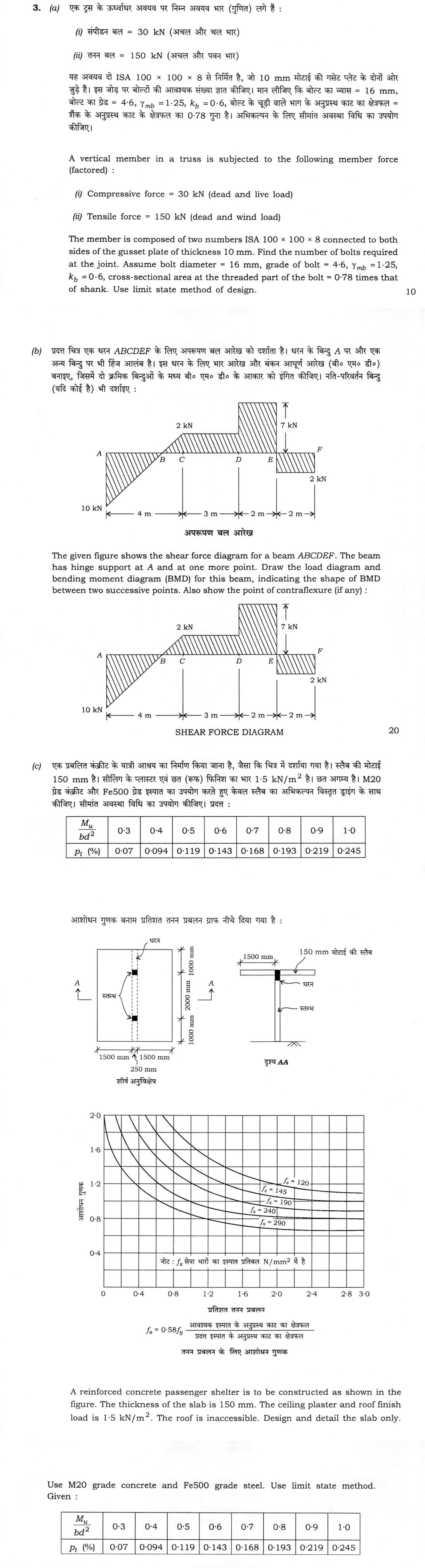
The given figure shows the shear force diagram for a beam ABCDEF. The beam has hinge support at A and at one more point. Draw the load diagram and bending moment diagram (BMD) for this beam, indicating the shape of BMD between two successive points. Also show the point of contraflexure (if any) : 20 marks
A reinforced concrete passenger shelter is to be constructed as shown in the figure. The thickness of the slab is 150 mm. The ceiling plaster and roof finish load is 1·5 kN/m². The roof is inaccessible. Design and detail the slab only.
Use M20 grade concrete and Fe500 grade steel. Use limit state method. Given :
[Table] Mu/bd² : 0·3 | 0·4 | 0·5 | 0·6 | 0·7 | 0·8 | 0·9 | 1·0 pt (%) : 0·07 | 0·094 | 0·119 | 0·143 | 0·168 | 0·193 | 0·219 | 0·245
Modification Factor vs. Percentage Tension Reinforcement graph is given below :
[Diagram — TOP PLAN : Beam (solid black squares), Column, vertical dimensions 1000 mm, 2000 mm, 1000 mm; horizontal dimensions 1500 mm, 250 mm, 1500 mm; section arrows A—A. Diagram — VIEW AA : 1500 mm, 150 mm thickness slab, Beam, Column.]
[Graph — MODIFICATION FACTOR (vertical axis 0·4, 0·8, 1·2, 1·6, 2·0) vs. PERCENTAGE TENSION REINFORCEMENT (horizontal axis 0, 0·4, 0·8, 1·2, 1·6, 2·0, 2·4, 2·8, 3·0); curves for fs = 120, fs = 145, fs = 190, fs = 240, fs = 290. Note : fs is steel stress of service loads in N/mm². fs = 0·58 fy × (Area of cross-section of steel required / Area of cross-section of steel provided).]
MODIFICATION FACTOR FOR TENSION REINFORCEMENT 20 marks
हिंदी में प्रश्न पढ़ें
एक ट्रस के ऊर्ध्वाधर अवयव पर निम्न अवयव भार (गुणित) लगे हैं :
संपीडन बल = 30 kN (अचल और चल भार)
तनन बल = 150 kN (अचल और पवन भार)
यह अवयव दो ISA 100 × 100 × 8 से निर्मित है, जो 10 mm मोटाई की गसेट प्लेट के दोनों ओर जुड़े हैं। इस जोड़ पर बोल्टों की आवश्यक संख्या ज्ञात कीजिए। मान लीजिए कि बोल्ट का व्यास = 16 mm, बोल्ट का ग्रेड = 4·6, γ_mb = 1·25, k_b = 0·6, बोल्ट के चूड़ी वाले भाग के अनुप्रस्थ काट का क्षेत्रफल = शैंक के अनुप्रस्थ काट के क्षेत्रफल का 0·78 गुना है। अभिकल्पन के लिए सीमांत अवस्था विधि का उपयोग कीजिए। (10 अंक)
प्रदत्त चित्र एक धरन ABCDEF के लिए अपरूपण बल आरेख को दर्शाता है। धरन के बिन्दु A पर और एक अन्य बिन्दु पर भी हिंज आलंब है। इस धरन के लिए भार आरेख और बंकन आघूर्ण आरेख (बी० एम० डी०) बनाइए, जिसमें दो क्रमिक बिन्दुओं के मध्य बी० एम० डी० के आकार को इंगित कीजिए। नति-परिवर्तन बिन्दु (यदि कोई है) भी दर्शाइए : (20 अंक)
एक प्रबलित कंक्रीट के यात्री आश्रय का निर्माण किया जाना है, जैसा कि चित्र में दर्शाया गया है। स्लैब की मोटाई 150 mm है। सीलिंग के प्लास्टर एवं छत (रूफ) फिनिश का भार 1·5 kN/m² है। छत अगम्य है। M20 ग्रेड कंक्रीट और Fe500 ग्रेड इस्पात का उपयोग करते हुए केवल स्लैब का अभिकल्पन विस्तृत ड्राइंग के साथ कीजिए। सीमांत अवस्था विधि का उपयोग कीजिए। प्रदत्त :
| M_u/(bd²) | 0·3 | 0·4 | 0·5 | 0·6 | 0·7 | 0·8 | 0·9 | 1·0 |
|---|---|---|---|---|---|---|---|---|
| p_t (%) | 0·07 | 0·094 | 0·119 | 0·143 | 0·168 | 0·193 | 0·219 | 0·245 |
आशोधन गुणक बनाम प्रतिशत तनन प्रबलन ग्राफ नीचे दिया गया है : धन, स्तम्भ, 1500 mm, 1500 mm, 250 mm, 2000 mm, 1000 mm, 1000 mm, शीर्ष अनुविक्षेप, A, A, दृश्य AA, 150 mm मोटाई की स्लैब (ग्राफ अक्ष : 2·0, 1·6, 1·2, 0·8, 0·4 — आशोधन गुणक; 0, 0·4, 0·8, 1·2, 1·6, 2·0, 2·4, 2·8, 3·0 — प्रतिशत तनन प्रबलन; f_s = 120, f_s = 145, f_s = 190, f_s = 240, f_s = 290) नोट : f_s सैद्धांतिक भारों का इस्पात प्रतिबल N/mm² में है f_s = 0·58 f_y × आवश्यक इस्पात के अनुप्रस्थ काट का क्षेत्रफल / प्रदत्त इस्पात के अनुप्रस्थ काट का क्षेत्रफल तनन प्रबलन के लिए आशोधन गुणक (20 अंक)
Model answer
Drafted with AI by UPSC Answer Check against this question's marking rubric, to the expected length. UPSC does not publish answers for Mains — this is one way to score well, not an official key. How we build rubrics and answers.
(a) Number of bolts for the truss member joint (10 marks)
The member carries a factored compression of 30 kN and a factored tension of 150 kN, so the tension governs. Two ISA 100 × 100 × 8 are connected on either side of a 10 mm gusset plate, so each bolt is in double shear. Data: d = 16 mm (hole d₀ = 18 mm), grade 4.6 (f_ub = 400 MPa), γ_mb = 1.25, k_b = 0.6, and a plate of fu = 410 MPa (Fe 410 steel, assumed). The threaded area is A_nb = 0.78 × (π/4) × 16² = 0.78 × 201.1 = 156.8 mm², and the shank area is A_sb = 201.1 mm².
Shear capacity (IS 800:2007 cl. 10.3.3), with one shear plane through the threaded part and one through the shank:
V_dsb = (f_ub/√3)(n_n A_nb + n_s A_sb)/γ_mb = (400/√3)(156.8 + 201.1)/1.25 = 66.1 kN.
Bearing capacity (cl. 10.3.4): the bearing thickness is the smaller of the gusset (10 mm) and the two angle legs (2 × 8 = 16 mm), so t = 10 mm.
V_dpb = 2.5 k_b d t f_u/γ_mb = 2.5 × 0.6 × 16 × 10 × 410/1.25 = 78.7 kN.
Bolt value = the smaller = 66.1 kN.
Number of bolts = 150/66.1 = 2.27, so provide 3 bolts of 16 mm, grade 4.6, in a line. Check the spacing: pitch not less than 2.5d = 40 mm (provide 50 mm) and edge distance not less than 1.5d₀ = 27 mm (provide 30 mm).
(b) Loading and bending moment diagram from the shear force diagram (20 marks)
The shear force diagram is read from the figure as follows: at A the ordinate is 10 kN, plotted below the axis; it varies linearly, crossing zero at B, to 2 kN above the axis at C (4 m from A); it is constant at 2 kN above the axis from C to D (3 m); it steps up to 7 kN above the axis at D and stays constant to E (2 m); it drops to 2 kN below the axis at E and is constant to F (2 m), closing to zero at F. The 10 kN plotted below the axis at A is the upward reaction of the hinge, so ordinates below the axis are taken as positive in this reading and the loads are gravity loads (reversing the sign convention would reverse every load).
Reconstruction of the loads:
- At A: a jump of 10 kN, an upward reaction R_A = 10 kN at the hinge support.
- A to C: the shear changes linearly by 12 kN over 4 m, so a uniformly distributed load of 12/4 = 3 kN/m acts over AC (total 12 kN).
- C to D: constant shear, so no load.
- At D: a jump of 5 kN (from 2 to 7), a downward point load of 5 kN at D.
- D to E: constant, no load.
- At E: a jump of 9 kN (from 7 kN above the axis to 2 kN below it), the upward reaction R_E = 9 kN. This locates the second hinge support at E, 9 m from A.
- E to F: constant 2 kN, no load; at F the shear closes to zero through a downward point load of 2 kN at the free end.
Check: total downward load = 3 × 4 + 5 + 2 = 19 kN = 10 + 9. Moments about A: 12 × 2 + 5 × 7 + 2 × 11 = 81 = 9 × 9. ✓.
Bending moment (sagging positive, M = area of the shear diagram):
- A: M = 0 (hinge).
- B: shear is zero at x = 10/3 = 3.33 m from A, where the moment is maximum: M_B = 10 × 3.33 - 3 × 3.33²/2 = 16.67 kN·m.
- C: M_C = 10 × 4 - 3 × 4²/2 = 40 - 24 = 16.0 kN·m.
- D: M_D = 16.0 - 2 × 3 = 10.0 kN·m.
- E: M_E = 10.0 - 7 × 2 = -4.0 kN·m (hogging, at the support).
- F: M_F = -4.0 + 2 × 2 = 0.
Shape of the curve: from A to C it is a parabola (the shear varies linearly under the UDL) with a maximum at B; C to D is a straight line falling slowly (shear 2 kN); D to E is a steeper straight line (shear 7 kN); E to F is a straight line rising (shear 2 kN).
Point of contraflexure: between D and E, where M changes sign: 10 - 7x = 0, so x = 1.43 m from D, i.e. 8.43 m from A.

(c) Cantilever roof slab of the shelter (20 marks)
Data: slab 150 mm thick, projection 1500 mm on each side of a 250 mm central beam, M20, Fe500, ceiling plaster and roof finish 1.5 kN/m², inaccessible roof.
Effective depth. Exposure is moderate (a roof exposed to rain), so the nominal cover is 30 mm; assume 10 mm bars: d = 150 - 30 - 5 = 115 mm. Effective length of the cantilever (IS 456 cl. 22.2): the length to the face of the support plus half the effective depth = 1500 + 115/2 = 1557 mm.
Loads on a 1 m strip:
- Self-weight: 0.15 × 25 = 3.75 kN/m
- Ceiling plaster and finish: 1.5 kN/m
- Live load on an inaccessible roof (IS 875 Part 2): 0.75 kN/m
- Total w = 6.0 kN/m; factored w_u = 1.5 × 6.0 = 9.0 kN/m.
Design moment: M_u = w_u L²/2 = 9.0 × 1.557²/2 = 10.9 kN·m per metre width.
Steel. M_u/bd² = 10.9 × 10⁶/(1000 × 115²) = 0.826. From the table, p_t = 0.193 at 0.8 and 0.219 at 0.9, so by interpolation p_t = 0.200%.
A_st = 0.200 × 1000 × 115/100 = 230 mm² per metre. The minimum steel is 0.12% of bD = 180 mm², so 230 mm² governs.
Deflection check. The basic ratio for a cantilever is L/d = 7. Try 10 mm at 250 mm (314 mm²): f_s = 0.58 × 500 × 230/314 = 212 N/mm² and p_t = 0.27%, for which the chart gives a modification factor of about 1.85; the permitted L/d = 7 × 1.85 = 12.9, while the actual L/d = 1557/115 = 13.5, so it fails. Provide 10 mm at 200 mm c/c: A_st = 393 mm² (p_t = 0.34%), f_s = 0.58 × 500 × 230/393 = 170 N/mm², modification factor = 2.0 (the upper limit of the chart), permitted L/d = 7 × 2.0 = 14.0 > 13.5, so the deflection is acceptable.
Shear check. At d from the face: V_u = 9.0 × (1.5 - 0.115) = 12.5 kN, so τ_v = 12.5 × 10³/(1000 × 115) = 0.11 N/mm². For p_t = 0.34% and M20, τ_c = 0.40 N/mm² (IS 456 Table 19), and for a slab of depth 150 mm the factor k = 1.30, so kτ_c = 0.52 N/mm² > τ_v, and no shear reinforcement is needed.
Other checks. Maximum spacing of main bars: 3d = 345 mm and 300 mm, so 200 mm is within the limit. Development length L_d = 0.87 f_y φ/(4τ_bd) = 0.87 × 500 × 10/(4 × 1.92) = 566 mm; the top bars run continuously over the beam from one cantilever to the other, so anchorage is assured. Distribution steel: 0.12% of bD = 180 mm² per metre, so provide 8 mm at 250 mm c/c (201 mm²).
Detail: 150 mm slab; top main bars 10 mm at 200 mm c/c continuous over the beam and extending to the free edges with 30 mm cover; 8 mm at 250 mm c/c distribution bars below and at right angles to the main bars.

How this answer will be evaluated
Evaluation rubric
Each sub-part is marked on its own, against the marks and word limit printed on the paper.
- (a) Using IS 800 limit state method, find the number of 16 mm grade 4.6 bolts for the joint of a double-angle truss member (governing tension 150 kN): double-shear capacity, bearing capacity, bolt value, number. 10 marks
Must cover
- Tension of 150 kN governs over 30 kN compression
- Shear capacity V_dsb = (f_ub/√3)(A_nb + A_sb)/γ_mb = 66.1 kN, with A_nb = 0.78 A_sb
- Bearing V_dpb = 2.5 k_b d t f_u/γ_mb = 78.7 kN with t = 10 mm (gusset)
- Bolt value 66.1 kN and n = 150/66.1 = 2.27, so 3 bolts
Loses marks
- Using the 16 mm of angle legs in bearing rather than the 10 mm gusset.
- Using single shear or full-shank area in both shear planes.
- Rounding down to 2 bolts.
Earns more
- Explanation of one plane through the threaded portion and one through the shank.
- Choice of the smaller of the gusset and the angle thicknesses for bearing.
Extra mark
- Pitch and edge distance checks (40 mm and 27 mm minimum)
- (b) From the shear force diagram of beam ABCDEF reconstruct the loading (locating the second hinge support), then draw the bending moment diagram, stating the curve shape between points and the point of contraflexure. 20 marks
Must cover
- Loads: R_A = 10 kN, UDL 3 kN/m over AC (4 m), 5 kN at D, R_E = 9 kN (second support), 2 kN at F
- Equilibrium check: 19 kN down = 10 + 9, and moments about A balance
- BM: 0 at A, 16.67 at 3.33 m (B), 16.0 at C, 10.0 at D, -4.0 at E, 0 at F
- Parabolic A to C, straight lines C-D, D-E, E-F; contraflexure 8.43 m from A (1.43 m beyond D)
Loses marks
- Placing the second support at D or F.
- Straight line in place of the parabola under the UDL.
- Missing the point of contraflexure.
Earns more
- Load diagram drawn with the supports marked.
- Sign convention of the diagram stated.
- (c) Design and detail the 150 mm thick cantilever roof slab (1500 mm projection each side, M20, Fe500): loads, design moment, steel from the table, and shear and deflection checks with the modification chart, ending in a reinforcement detail. 20 marks
Must cover
- Loads: 3.75 + 1.5 + 0.75 = 6.0 kN/m², w_u = 9.0 kN/m; M_u = 10.9 kN·m/m for L = 1557 mm
- M_u/bd² = 0.826 with d = 115 mm; p_t = 0.200%; A_st = 230 mm²/m (above 180 minimum)
- Deflection: 10 mm at 200 (393 mm²), f_s = 170, MF = 2.0, L/d = 13.5 ≤ 14
- Shear: τ_v = 0.11 < kτ_c = 0.52 N/mm²; detail 10 mm at 200 top, 8 mm at 250 distribution, with a sketch
Loses marks
- Live load of 1.5 or more on an inaccessible roof.
- Not checking deflection with the modification factor, or omitting the top steel over the beam.
- Steel less than the minimum 0.12%.
Earns more
- Live load of 0.75 kN/m² for an inaccessible roof.
- Effective length to the face plus d/2, and development length check.
What "Design" is asking you to do
Produce a specification that meets the given brief and demonstrate that it does. In civil and electrical papers the design is incomplete until it is expressed in buildable numbers — diameter, spacing, section, component value — and checked back against every limit stated.
Structure that answers it
Requirements and permissible values listed → code clause or design basis adopted → proportioning calculations → the specification in final dimensions → check against each requirement → sketch
Where marks are lost
Stopping at a required area or a required value without converting it into the bar size, spacing or component actually provided. The provided-against-required comparison and the serviceability or stability check are separately marked and routinely left out.
Practice this exact question
Write your answer and it is marked point by point against the model answer above — what you covered, what you missed, what you got wrong.
Evaluate my answer →More from Civil Engineering 2026 Paper I
- Q1 (a) A frictionless pulley A as shown in the figure is supported by two bars AB and AC whi…
- Q2 (a) Using limit state method, design a reinforced concrete circular column (with lateral…
- Q3 (a) A vertical member in a truss is subjected to the following member force (factored) :…
- Q4 (a) Three bodies of weights 200 N, 800 N and 400 N are connected with inextensible string…
- Q5 (a) A free jet of water with constant cross-section area of 0·01 m² is deflected by a hin…
- Q6 (a) Assuming the law for the velocity distribution in the boundary layer as $\dfrac{v}{V}…