Paper II — Q3
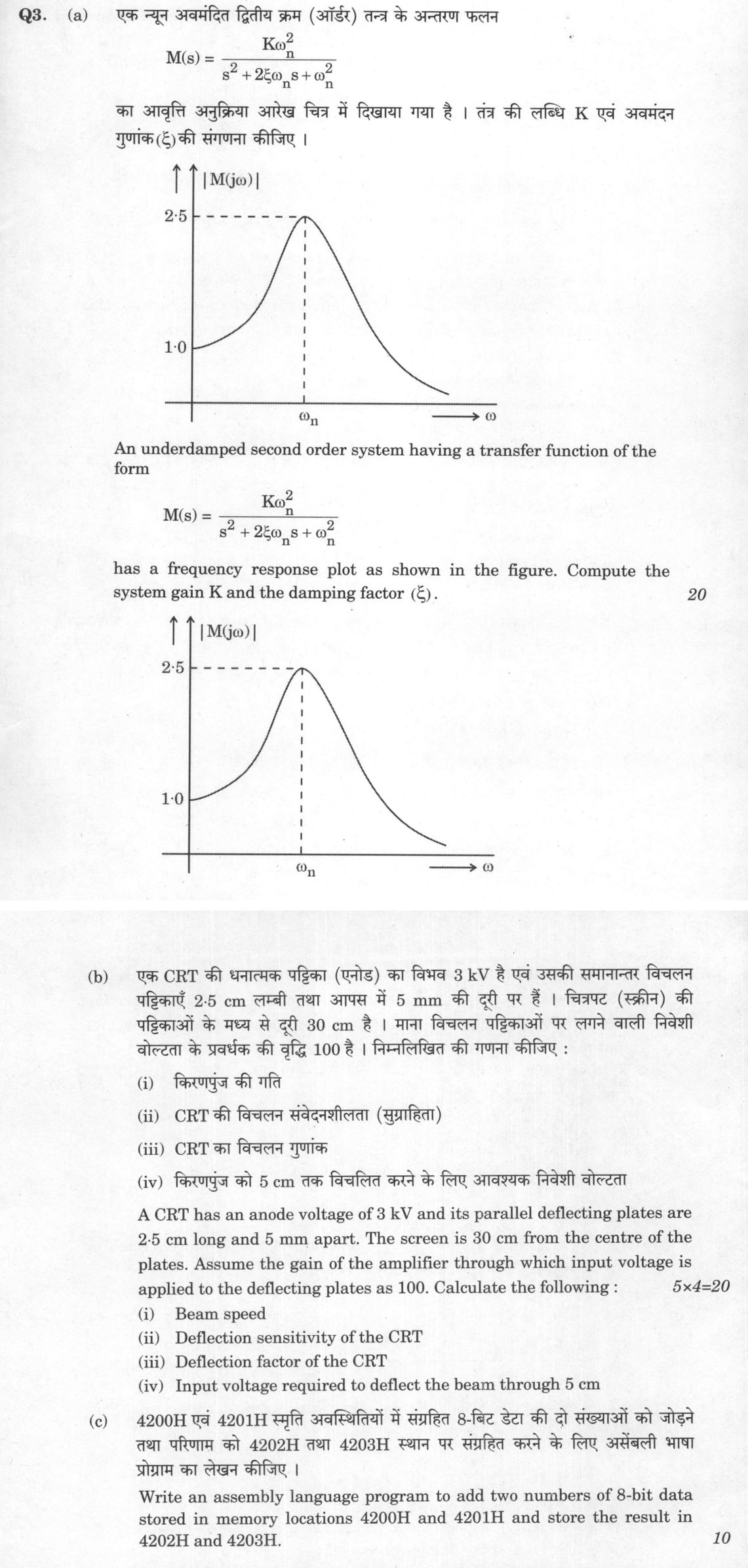
(a) An underdamped second order system having a transfer function of the form M(s) = (Kωₙ²)/(s² + 2ξωₙ s + ωₙ²) has a frequency…
An underdamped second order system having a transfer function of the form
M(s) = (Kωₙ²)/(s² + 2ξωₙ s + ωₙ²)
has a frequency response plot as shown in the figure. Compute the system gain K and the damping factor (ξ). 20 marks
A CRT has an anode voltage of 3 kV and its parallel deflecting plates are 2·5 cm long and 5 mm apart. The screen is 30 cm from the centre of the plates. Assume the gain of the amplifier through which input voltage is applied to the deflecting plates as 100. Calculate the following : 20 marks
Beam speed
Deflection sensitivity of the CRT
Deflection factor of the CRT
Input voltage required to deflect the beam through 5 cm
Write an assembly language program to add two numbers of 8-bit data stored in memory locations 4200H and 4201H and store the result in 4202H and 4203H. 10 marks
हिंदी में प्रश्न पढ़ें
एक न्यून अवमंदित द्वितीय क्रम (ऑर्डर) तंत्र के अंतरण फलन
M(s) = (Kωₙ²)/(s² + 2ξωₙ s + ωₙ²)
का आवृत्ति अनुक्रिया आरेख चित्र में दिखाया गया है । तंत्र की लब्धि K एवं अवमंदन गुणांक(ξ) की संगणना कीजिए । (20 अंक)
एक CRT की धनात्मक पट्टिका (एनोड) का विभव 3 kV है एवं उसकी समानांतर विचलन पट्टिकाएँ 2·5 cm लम्बी तथा आपस में 5 mm की दूरी पर हैं । चित्रपट (स्क्रीन) की पट्टिकाओं के मध्य से दूरी 30 cm है । माना विचलन पट्टिकाओं पर लगने वाली निवेशी वोल्टता के प्रवर्धक की वृद्धि 100 है । निम्नलिखित की गणना कीजिए : (20 अंक)
किरणपुंज की गति
CRT की विचलन संवेदनशीलता (सुग्राहिता)
CRT का विचलन गुणांक
किरणपुंज को 5 cm तक विचलित करने के लिए आवश्यक निवेशी वोल्टता
4200H एवं 4201H स्मृति अवस्थितियों में संग्रहित 8-बिट डेटा की दो संख्याओं को जोड़ने तथा परिणाम को 4202H तथा 4203H स्थान पर संग्रहित करने के लिए असेंबली भाषा प्रोग्राम का लेखन कीजिए । (10 अंक)
The figure this question refers to, in words
The question paper is a scan and the diagram did not survive as text. This is the figure as read from the original page — every component, value and label — so the question can be worked from the text below.
(a) A frequency response plot of magnitude |M(j*omega)| versus angular frequency omega. The vertical axis represents |M(j*omega)|, and the horizontal axis represents omega. At omega = 0, the curve starts at |M(j*omega)| = 1.0. As omega increases, the curve rises to a resonant peak with a maximum value of 2.5 occurring at omega = omega_n (marked by horizontal and vertical dashed lines leading to 2.5 on the vertical axis and omega_n on the horizontal axis, respectively). For omega > omega_n, the curve monotonically decreases towards zero.
Model answer
Written by UPSC Answer Check against this question's marking rubric, to the expected length. UPSC does not publish answers for Mains — this is one way to score well, not an official key.
(a) For the given transfer function, M(jω) = Kωₙ² / ((ωₙ² − ω²) + j 2ξωₙω).
At ω = 0, M(j0) = Kωₙ² / ωₙ² = K. The figure gives |M(j0)| = 1.0, hence K = 1.
At the marked frequency ω = ωₙ, M(jωₙ) = Kωₙ² / (j 2ξωₙ²) = K / (j 2ξ). So |M(jωₙ)| = K / (2ξ).
Using K = 1 and the figure value |M(jωₙ)| = 2.5, 1 / (2ξ) = 2.5 => 2ξ = 1 / 2.5 = 0.4 => ξ = 0.4 / 2 = 0.2.
Thus K = 1, ξ = 0.2. Since 0 < ξ < 1, the system is underdamped, as required.
(b) Given: V_a = 3 kV = 3000 V, plate length l = 2.5 cm = 0.025 m, plate separation d = 5 mm = 0.005 m, screen distance from centre of plates L = 30 cm = 0.30 m, amplifier gain A = 100.
(i) Beam speed The kinetic energy gained by the electron equals the potential energy from the anode voltage: (1/2) m v² = e V_a => v = √(2 e V_a / m).
Using e/m = 1.7588 × 10¹¹ C/kg, v = √(2 × 1.7588 × 10¹¹ × 3000) = √(1.0553 × 10¹⁵) ≈ 3.248 × 10⁷ m/s.
Beam speed = 3.25 × 10⁷ m/s approximately.
(ii) Deflection sensitivity Let V_d be the deflecting voltage. The time spent between plates is t = l / v. Vertical acceleration is a = e V_d / (m d). At plate exit, y₁ = (1/2) a t² = e V_d l² / (2 m d v²). Since v² = 2 e V_a / m, y₁ = V_d l² / (4 d V_a).
The slope at exit is v_y / v = e V_d l / (m d v²) = V_d l / (2 d V_a). The extra deflection from plate exit to screen is (V_d l / (2 d V_a)) (L − l/2).
Total deflection on screen: D = y₁ + extra deflection = V_d l² / (4 d V_a) + V_d l (L − l/2) / (2 d V_a) = V_d L l / (2 d V_a).
Hence deflection sensitivity S = D / V_d = L l / (2 d V_a) = (0.30 × 0.025) / (2 × 0.005 × 3000) = 0.0075 / 30 = 2.5 × 10⁻⁴ m/V = 0.25 mm/V.
Deflection sensitivity = 0.25 mm/V.
(iii) Deflection factor Deflection factor is the reciprocal of sensitivity: = 1 / S = 1 / (2.5 × 10⁻⁴) = 4 × 10³ V/m = 4 V/mm.
Deflection factor = 4 V/mm.
(iv) Input voltage for 5 cm deflection Required deflection D = 5 cm = 0.05 m. Deflecting voltage required: V_d = D / S = 0.05 / (2.5 × 10⁻⁴) = 200 V.
Amplifier gain A = 100, so V_in = V_d / A = 200 / 100 = 2 V.
Input voltage required = 2 V.
(c) Assuming 8085 assembly language, the program is:
LXI H, 4200H ; HL points to 4200H MOV A, M ; A = data at 4200H INX H ; HL points to 4201H ADD M ; A = A + data at 4201H, carry set if needed INX H ; HL points to 4202H MOV M, A ; store lower 8-bit sum at 4202H MVI A, 00H ; A = 00H ACI 00H ; add carry into A, so A = carry (0 or 1) INX H ; HL points to 4203H MOV M, A ; store carry at 4203H HLT ; stop
Thus the sum is stored at 4202H, and the carry is stored at 4203H. If there is no carry, 4203H contains 00H.
What "Calculate" is asking you to do
Apply the standard formula or schedule to data the question has already supplied — a table of readings, cost records, a balance sheet — and produce the number. The method is rarely in doubt; the marks sit in the named intermediate quantities, each of which has to appear as a labelled line.
Structure that answers it
Data as given → formula or standard treatment, named → substitution → each intermediate, labelled → result with units
Where marks are lost
Omitting an intermediate the marking scheme pays for separately, or rounding at an intermediate line so the final figure drifts. In commerce and accountancy, any figure in a statement that no numbered working note supports is treated as unearned.
How this answer will be evaluated
Approach
(a) calculate: given > formula > substitution > result with units > interpretation | (b) calculate: given > formula > substitution > result with units > interpretation | (c) explain: definition/context > points in order > small example > short close Full marks: Correct values with clear derivation; all CRT parameters calculated with units; assembly code is syntactically correct and handles carry.
Key points expected
- Identify DC gain |M(0)| = 1.0 from the plot
- Identify peak magnitude |M(ωn)| = 2.5 from the plot
- Relate DC gain to K to find K = 1
- Use peak magnitude formula to solve for ξ
- Calculate beam speed using anode voltage (3 kV)
- Calculate deflection sensitivity using plate length, spacing, and screen distance
- Calculate deflection factor as reciprocal of sensitivity
- Calculate input voltage for 5 cm deflection using amplifier gain (100)
Evaluation rubric
Each sub-part is marked on its own, against the marks and word limit printed on the paper.
- (a) Determine system gain K and damping factor ξ from the frequency response plot. 20 marks
calculate— given → formula → substitution → result with units → interpretation
Must cover
- Identify DC gain |M(0)| = 1.0 from the plot
- Identify peak magnitude |M(ωn)| = 2.5 from the plot
- Relate DC gain to K to find K = 1
- Use peak magnitude formula to solve for ξ
Loses marks
- Assumes K = 1 without deriving from DC gain
- Confuses peak frequency ωr with natural frequency ωn
- Formula application without reading values from the graph
Earns more
- Explicitly states M(0) = K
- Uses standard second-order peak magnitude formula
- Shows algebraic steps for solving ξ
Extra mark
- Verifies result by substituting back into transfer function
- (b) Compute beam speed, deflection sensitivity, deflection factor, and required input voltage. 20 marks
calculate— given → formula → substitution → result with units → interpretation
Must cover
- Calculate beam speed using anode voltage (3 kV)
- Calculate deflection sensitivity using plate length, spacing, and screen distance
- Calculate deflection factor as reciprocal of sensitivity
- Calculate input voltage for 5 cm deflection using amplifier gain (100)
Loses marks
- Forgets to account for amplifier gain in part (iv)
- Confuses deflection factor with deflection sensitivity
- Unit errors in length or voltage conversions
Earns more
- States formula for electron beam velocity v = sqrt(2eV/m)
- Clearly defines deflection sensitivity S = D/(L*Vd)
- Distinguishes between deflection voltage and input voltage
- Carries units in all intermediate steps
Extra mark
- Provides a diagram of the CRT deflection geometry
- (c) Write an assembly program to add two 8-bit numbers and store the 16-bit result. 10 marks
explain— definition/context → points in order → small example → short close
Must cover
- Loads data from memory locations 4200H and 4201H
- Performs addition of the two 8-bit numbers
- Stores the lower byte of the result in 4202H
- Stores the carry/upper byte of the result in 4203H
Loses marks
- Fails to store the carry in 4203H
- Uses incorrect memory addresses
- Logic error in the addition sequence
Earns more
- Uses appropriate load and store instructions (e.g., LDA, STA)
- Explicitly handles the carry bit for the second byte
- Includes comments explaining each step
Extra mark
- Includes a program termination instruction (e.g., HLT)
Practice this exact question
Write your answer and it is marked point by point against the model answer above — what you covered, what you missed, what you got wrong.
Evaluate my answer →More from Electrical Engineering 2024 Paper II
- Q1 (a) What are the limitations of (i) Proportional (P), (ii) Integral (I), (iii) Derivative…
- Q2 (a) The open-loop transfer function of a feedback control system incorporating a dead tim…
- Q3 (a) An underdamped second order system having a transfer function of the form M(s) = (Kωₙ…
- Q4 (a) The capacitance of a piezoelectric transducer is 2000 pF and charge sensitivity is 30…
- Q5 (a) The block diagram of a position control system is shown in the figure. Determine the…
- Q6 (a) Calculate the power loss in the transmission system given in the following figure. Th…