Paper II — Q5
(a) The block diagram of a position control system is shown in the figure. Determine the sensitivity of the closed loop transfer…
The block diagram of a position control system is shown in the figure. Determine the sensitivity of the closed loop transfer function T(s) with respect to G(s) and H(s) for 1 rad/sec. 10 marks
The disc in a single-phase energy meter rotates 1320 times when monitoring a 110 V, 3 A load at unity power factor over a period of 8 hours. Calculate the meter constant. If the meter makes 750 revolutions when measuring the energy supplied to a 110 V, 5 A load for 3 hours, determine the load power factor. 5+5=10 marks
Write the bus admittance matrix for the network shown in the figure. 10 marks
A single core cable without grading operates at 14 kV. The conductor radius is 1·12 cm and insulation radius is 2·75 cm. If cable is with inter-sheath grading at suitable radius, then calculate the maximum operating voltage of the cable. 10 marks
How does information get passed from one layer to the next in the Internet model? How do the layers of the Internet model correlate to the layers of the OSI model? 6+4=10 marks
हिंदी में प्रश्न पढ़ें
एक अवस्था नियंत्रण प्रणाली का खण्ड आरेख चित्र में प्रदर्शित किया गया है । 1 rad/sec के लिए G(s) एवं H(s) के सापेक्ष संवृत पाश अंतरण फलन T(s) की संवेदनशीलता (सुग्राहिता) का निर्धारण कीजिए । 10 अंक
जब 110 V, 3 A इकाई शक्ति गुणांक वाले भार को 8 घंटे की समय अवधि के लिए एक एकल-कला ऊर्जा मीटर की निगरानी में रखा जाता है, इस दौरान मीटर का चक्र (डिस्क) 1320 बार घूमता है । मीटर स्थिरांक की गणना कीजिए । यदि 110 V, 5 A भार को प्रदान की गई ऊर्जा का मापन 3 घंटे की अवधि तक किया जाता है, तो मीटर का चक्र 750 बार घूमता है; भार शक्ति गुणांक की गणना कीजिए । 5+5=10 अंक
चित्र में प्रदर्शित जालतंत्र (नेटवर्क) के लिए बस प्रवेश्यता आव्यूह लिखिए । 10 अंक
एक अश्रेणीकृत एकल कोर केबल का परिचालन 14 kV पर किया जाता है । केबल के चालक की त्रिज्या 1·12 cm और विद्युतरोधन परत की त्रिज्या 2·75 cm है । यदि केबल में उचित त्रिज्या पर श्रेणीकृत अंतःखोल (इंटर-शीथ) प्रदत की जाए, तो केबल की अधिकतम परिचालन वोल्टता की गणना कीजिए । 10 अंक
अंतरजाल (इंटरनेट) प्रतिरूप में सूचनाओं को एक परत से दूसरी परत तक कैसे पहुँचाया जाता है ? किसी अंतरजाल प्रतिरूप की परतों को OSI प्रतिरूप की परतों से कैसे सहसंबंधित किया जाता है ? 6+4=10 अंक
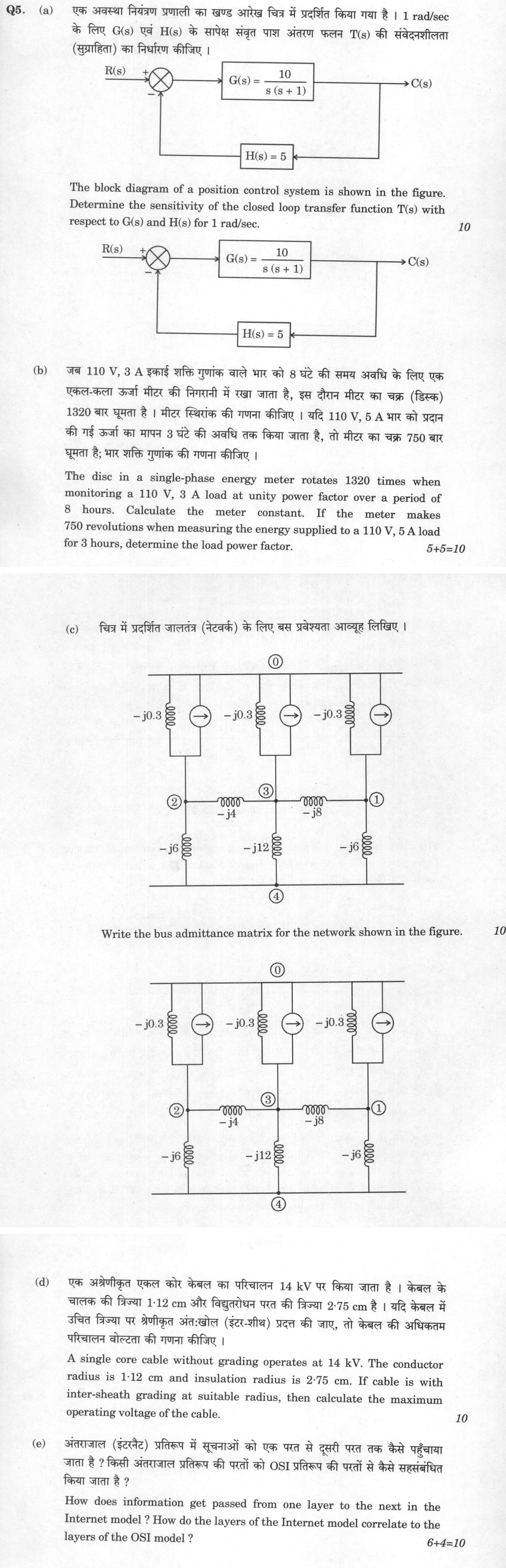
The figure this question refers to, in words
The question paper is a scan and the diagram did not survive as text. This is the figure as read from the original page — every component, value and label — so the question can be worked from the text below.
(a) Block diagram of a position control system: Input R(s) enters a summing junction (with a plus sign on the R(s) path and a minus sign on the feedback path). The output of the summing junction goes to a block labeled G(s) = 10 / (s(s+1)). The output of G(s) is C(s). The output C(s) is fed back through a block labeled H(s) = 5, whose output connects to the minus input of the summing junction.
(c) A power system network diagram with five buses labeled 0, 1, 2, 3, and 4. Bus 0 is at the top, buses 1, 2, and 3 are in the middle row, and bus 4 is at the bottom. Bus 0 is connected to bus 2 via a parallel combination of an inductor with reactance -j0.3 and a current source pointing right. Bus 0 is connected to bus 3 via a parallel combination of an inductor with reactance -j0.3 and a current source pointing right. Bus 0 is connected to bus 1 via a parallel combination of an inductor with reactance -j0.3 and a current source pointing right. Bus 2 is connected to bus 3 via an inductor with reactance -j4. Bus 3 is connected to bus 1 via an inductor with reactance -j8. Bus 2 is connected to bus 4 via an inductor with reactance -j6. Bus 3 is connected to bus 4 via an inductor with reactance -j12. Bus 1 is connected to bus 4 via an inductor with reactance -j6.
Model answer
Written by UPSC Answer Check against this question's marking rubric, to the expected length. UPSC does not publish answers for Mains — this is one way to score well, not an official key.
(a) For the negative-feedback system,
T(s) = G(s)/[1 + G(s)H(s)].
The relative sensitivity functions are defined as
S_G = (∂T/T)/(∂G/G) = 1/[1 + G(s)H(s)]
and
S_H = (∂T/T)/(∂H/H) = −G(s)H(s)/[1 + G(s)H(s)].
Given:
G(s) = 10/[s(s + 1)], H(s) = 5.
At ω = 1 rad/s, s = j1. Therefore,
G(j1)H(j1) = [10/(j1(j1 + 1))] × 5 = 50/[j1(j1 + 1)].
Now j1(j1 + 1) = j1 + j² = −1 + j. Hence,
G(j1)H(j1) = 50/(−1 + j) = 50(−1 − j)/[(−1)² + 1²] = 50(−1 − j)/2 = −25 − j25.
Thus,
1 + G(j1)H(j1) = 1 − 25 − j25 = −24 − j25.
So,
S_G = 1/(−24 − j25) = (−24 + j25)/(24² + 25²) = (−24 + j25)/1201.
Similarly,
S_H = −(−25 − j25)/(−24 − j25) = (25 + j25)/(−24 − j25).
Multiplying numerator and denominator by the conjugate (−24 + j25):
S_H = [(25 + j25)(−24 + j25)]/1201 = (−1225 + j25)/1201.
Hence at 1 rad/s,
S_G = (−24 + j25)/1201 = −0.01998 + j0.02082
and
S_H = (−1225 + j25)/1201 = −1.01998 + j0.02082.
Their magnitudes are
|S_G| = 1/√1201 = 0.02886,
|S_H| = √(1225² + 25²)/1201 = 1.0202.
These are dimensionless sensitivity values, valid for small parameter variations in a linear system.
(b)(i) Energy consumed by the load is
Energy = V I cosφ × time.
For 110 V, 3 A, unity power factor, and 8 hours:
Energy = 110 × 3 × 1 × 8 = 2640 Wh = 2.64 kWh.
The disc makes 1320 revolutions for this energy. Therefore the meter constant is
K = revolutions/energy = 1320/2.64 = 500 rev/kWh.
Meter constant K = 500 rev/kWh.
(b)(ii) In the second test, the meter makes 750 revolutions. Using K = 500 rev/kWh,
Energy recorded = 750/500 = 1.5 kWh.
The apparent energy supplied is
V I t = 110 × 5 × 3 = 1650 Wh = 1.65 kWh.
Thus the load power factor is
cosφ = actual energy/apparent energy = 1.5/1.65 = 10/11 = 0.9091.
Load power factor = 10/11 = 0.9091 lagging (assuming the usual inductive load; the question gives only the magnitude).
(c) Taking bus 0 as the reference bus, the bus admittance matrix is formed for buses 1, 2, 3, 4. The current sources do not enter the Y-bus matrix; they contribute only to the current-injection vector.
The branch admittances are:
y₀₁ = y₀₂ = y₀₃ = 1/(−j0.3) = j10/3,
y₁₃ = 1/(−j8) = j1/8,
y₂₃ = 1/(−j4) = j1/4,
y₂₄ = 1/(−j6) = j1/6,
y₁₄ = 1/(−j6) = j1/6,
y₃₄ = 1/(−j12) = j1/12.
Using Y_ii = sum of admittances connected to bus i and Y_ij = −y_ij for i ≠ j:
Y₁₁ = j10/3 + j1/8 + j1/6 = j29/8,
Y₂₂ = j10/3 + j1/4 + j1/6 = j15/4,
Y₃₃ = j10/3 + j1/4 + j1/8 + j1/12 = j91/24,
Y₄₄ = j1/6 + j1/12 + j1/6 = j5/12.
Therefore, with bus order 1, 2, 3, 4,
Ybus = j ×
[ 29/8, 0, −1/8, −1/6 ; 0, 15/4, −1/4, −1/6 ; −1/8, −1/4, 91/24, −1/12 ; −1/6, −1/6, −1/12, 5/12 ]
This is the required bus admittance matrix in per unit. Bus 0 is the reference and hence does not appear as a row or column.
(d) For the ungraded single-core cable, the maximum electric stress is
E_max = V/[r ln(R/r)].
Here r = 1.12 cm, R = 2.75 cm, V = 14 kV.
R/r = 2.75/1.12 = 2.45536.
ln(R/r) = ln(2.45536) = 0.89827.
Thus,
E_max = 14/[1.12 × 0.89827] = 13.9156 kV/cm.
With one intersheath at radius r_m, let V₁ be the voltage from conductor to intersheath and V₂ be the voltage from intersheath to sheath. For equal maximum stresses in the two dielectric layers,
V₁ = E_max r ln(r_m/r),
V₂ = E_max r_m ln(R/r_m).
Total voltage is
V = E_max [ r ln(r_m/r) + r_m ln(R/r_m) ].
For the optimum or “suitable” intersheath radius, maximise the bracket with respect to r_m:
d/dr_m [ r ln(r_m/r) + r_m ln(R/r_m) ] = 0.
This gives
r/r_m + ln(R/r_m) − 1 = 0.
Solving numerically,
R/r_m = 1.4848,
so
r_m = R/1.4848 = 2.75/1.4848 = 1.852 cm.
The bracket then becomes
r ln(r_m/r) + r_m ln(R/r_m) = 1.29545 cm.
Therefore the maximum operating voltage is
V_max = E_max × 1.29545 = 13.9156 × 1.29545 = 18.03 kV.
Maximum operating voltage ≈ 18.03 kV (r.m.s.).
(e)(i) In the Internet model, information is passed from one layer to the next by encapsulation and decapsulation. At the sender, the application layer creates the message and passes it to the transport layer. The transport layer adds a TCP or UDP header, forming a segment or datagram, and passes it to the Internet layer. The Internet layer adds an IP header, forming a packet, and passes it to the network-access or link layer. The link layer adds its frame header and trailer, forming a frame, and passes it to the physical layer for transmission as bits.
At the receiver, the process is reversed. The physical layer receives bits and passes them to the link layer. The link layer removes the frame header and trailer and passes the IP packet to the Internet layer. The Internet layer removes the IP header and passes the segment or datagram to the transport layer. The transport layer removes the TCP or UDP header and delivers the data to the correct application process. Thus each layer provides a service to the layer above and uses the service of the layer below. Peer layers communicate logically through protocols, while actual data transfer between adjacent layers occurs through interfaces and service access points such as ports and protocol numbers.
(e)(ii) The TCP/IP Internet model is usually described with four layers, while the OSI model has seven layers. Their correlation is:
- Internet Application layer corresponds to OSI Application, Presentation and Session layers.
- Internet Transport layer corresponds to OSI Transport layer.
- Internet Internet layer corresponds to OSI Network layer.
- Internet Network Access or Link layer corresponds to OSI Data Link and Physical layers.
In the five-layer teaching version of the Internet model, the correspondence is:
- Application → OSI Application, Presentation, Session.
- Transport → OSI Transport.
- Network/Internet → OSI Network.
- Data Link → OSI Data Link.
- Physical → OSI Physical.
Thus the Internet model is more practical and protocol-oriented, while the OSI model is a more detailed reference model.
What "Solve" is asking you to do
Choose the method, then carry it through to a final answer. Identifying what kind of problem this is and why that method applies is the first thing marked; a correct figure arrived at invisibly earns almost nothing.
Structure that answers it
Given data and what is required → method chosen, with the reason it applies → set-up (equation, circuit, free body, trial balance) → working, step by step → answer with units and any condition of validity
Where marks are lost
Doing the middle steps mentally and writing only the result. In mathematics papers, a further loss comes from giving a decimal where the exact value in surds or fractions was wanted, or from skipping the justification a part explicitly asks for.
How this answer will be evaluated
Approach
(a) calculate: given > formula > substitution > result with units > interpretation | (b) calculate: given > formula > substitution > result with units > interpretation | (c) map: locate accurately > label > one line on why it matters | (d) calculate: given > formula > substitution > result with units > interpretation | (e) explain: definition/context > points in order > small example > short close Full marks: All parts with complete derivations, correct formulas, and clear presentation.
Key points expected
- Closed loop transfer function T(s) derived
- Sensitivity formula S_T^G = 1/(1+GH) applied
- Sensitivity formula S_T^H = -GH/(1+GH) applied
- Substitution of s=j1 into G(s) and H(s)
- Energy calculation for first case (kWh)
- Meter constant formula (rev/kWh) applied
- Energy calculation for second case
- Power factor formula (P/VI) applied
Evaluation rubric
Each sub-part is marked on its own, against the marks and word limit printed on the paper.
- (a) Sensitivity of T(s) w.r.t G(s) and H(s) at s=j1. 10 marks
calculate— given → formula → substitution → result with units → interpretation
Must cover
- Closed loop transfer function T(s) derived
- Sensitivity formula S_T^G = 1/(1+GH) applied
- Sensitivity formula S_T^H = -GH/(1+GH) applied
- Substitution of s=j1 into G(s) and H(s)
Loses marks
- Missing closed loop transfer function
- Incorrect sensitivity formula sign
Earns more
- Explicit calculation of G(j1) and H(j1)
- Final sensitivity values in rectangular form
Extra mark
- Block diagram reduction shown
- (b) Meter constant and load power factor. 10 marks
calculate— given → formula → substitution → result with units → interpretation
Must cover
- Energy calculation for first case (kWh)
- Meter constant formula (rev/kWh) applied
- Energy calculation for second case
- Power factor formula (P/VI) applied
Loses marks
- Incorrect energy calculation
- Missing power factor formula
Earns more
- Units clearly stated for energy and constant
- Step-by-step substitution shown
Extra mark
- Verification of meter constant units
- (c) Bus admittance matrix for the network. 10 marks
map— locate accurately → label → one line on why it matters
Must cover
- All branch admittances calculated
- Diagonal elements (self-admittances) correct
- Off-diagonal elements (mutual admittances) correct
- Matrix dimension matches number of buses
Loses marks
- Incorrect admittance calculation
- Missing off-diagonal elements
Earns more
- Clear labeling of bus numbers
- Symmetry of matrix verified
Extra mark
- Network diagram with admittances labeled
- (d) Maximum operating voltage with inter-sheath grading. 10 marks
calculate— given → formula → substitution → result with units → interpretation
Must cover
- Optimal sheath radius formula applied
- Voltage distribution across layers calculated
- Maximum stress condition used
- Final voltage in kV with units
Loses marks
- Incorrect radius calculation
- Missing voltage distribution
Earns more
- Comparison with ungraded cable voltage
- Stress distribution diagram
Extra mark
- Derivation of optimal radius formula
- (e) Information flow and OSI correlation. 10 marks
explain— definition/context → points in order → small example → short close
Must cover
- Layer-to-layer data transfer mechanism
- Encapsulation/decapsulation process
- Internet model layers listed
- OSI model layers listed
Loses marks
- Missing encapsulation explanation
- Incorrect layer correspondence
Earns more
- Table correlating Internet and OSI layers
- Example of data packet transformation
Extra mark
- Diagram showing layer correspondence
Practice this exact question
Write your answer and it is marked point by point against the model answer above — what you covered, what you missed, what you got wrong.
Evaluate my answer →More from Electrical Engineering 2024 Paper II
- Q2 (a) The open-loop transfer function of a feedback control system incorporating a dead tim…
- Q3 (a) An underdamped second order system having a transfer function of the form M(s) = (Kωₙ…
- Q4 (a) The capacitance of a piezoelectric transducer is 2000 pF and charge sensitivity is 30…
- Q5 (a) The block diagram of a position control system is shown in the figure. Determine the…
- Q6 (a) Calculate the power loss in the transmission system given in the following figure. Th…
- Q7 (a) Calculate the real and reactive power at sending end of a transmission line while del…
- Q8 (a) Two sources M₁ and M₂ emit messages x₁, x₂, x₃ and y₁, y₂, y₃ with the joint probabil…