Paper II — Q7
(a) A 3-phase line is terminated by a star-connected resistive load of 800 ohm per phase. The line conductors are equilaterally…
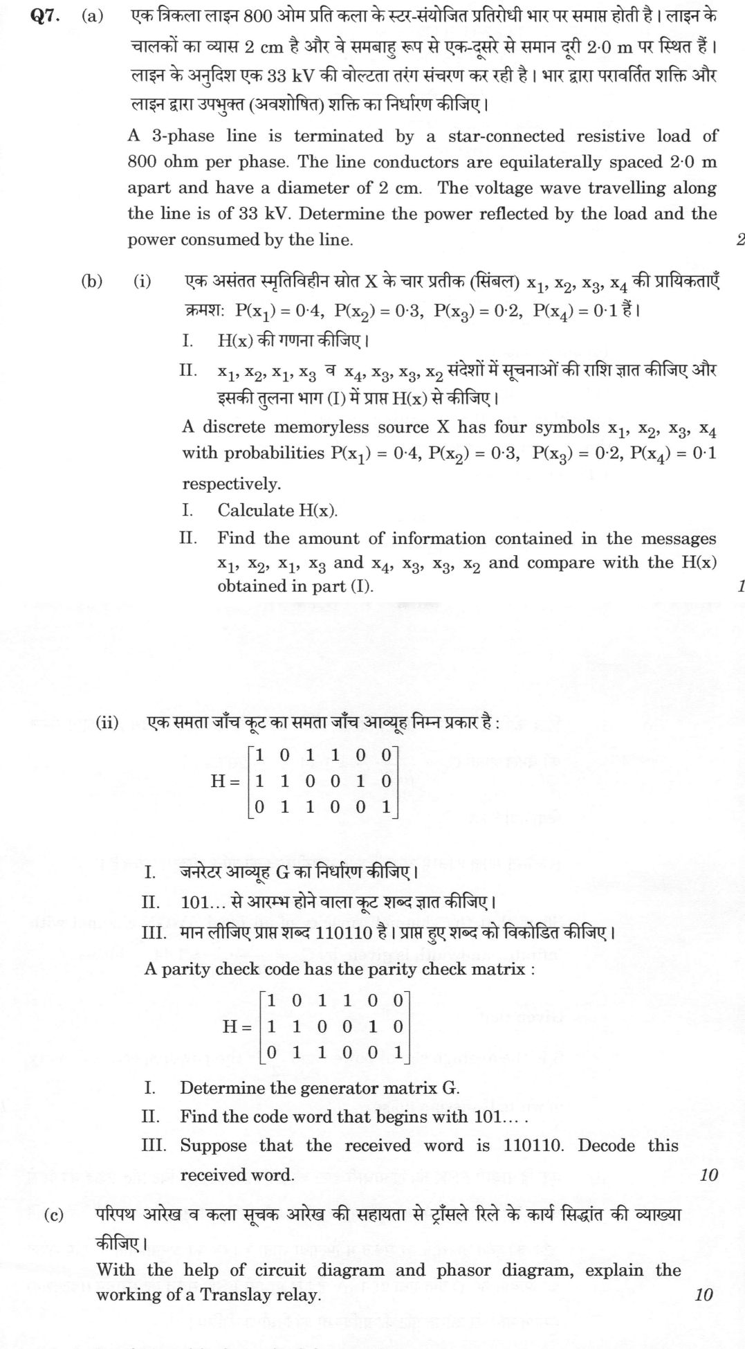
A 3-phase line is terminated by a star-connected resistive load of 800 ohm per phase. The line conductors are equilaterally spaced 2·0 m apart and have a diameter of 2 cm. The voltage wave travelling along the line is of 33 kV. Determine the power reflected by the load and the power consumed by the line. 20 marks
A discrete memoryless source X has four symbols x₁, x₂, x₃, x₄ with probabilities P(x₁) = 0·4, P(x₂) = 0·3, P(x₃) = 0·2, P(x₄) = 0·1 respectively. I. Calculate H(x). II. Find the amount of information contained in the messages x₁, x₂, x₁, x₃ and x₄, x₃, x₃, x₂ and compare with the H(x) obtained in part (I). 10 marks
A parity check code has the parity check matrix : H = [ 1 0 1 1 0 0 1 1 0 0 1 0 0 1 1 0 0 1 ] I. Determine the generator matrix G. II. Find the code word that begins with 101... . III. Suppose that the received word is 110110. Decode this received word. 10 marks
With the help of circuit diagram and phasor diagram, explain the working of a Translay relay. 10 marks
हिंदी में प्रश्न पढ़ें
एक त्रिकला लाइन 800 ओम प्रति कला के स्टार-संयोजित प्रतिरोधी भार पर समाप्त होती है। लाइन के चालकों का व्यास 2 cm है और वे समबाहु रूप से एक-दूसरे से समान दूरी 2·0 m पर स्थित हैं। लाइन के अनुदिश एक 33 kV की वोल्टता तरंग संचरण कर रही है। भार द्वारा परावर्तित शक्ति और लाइन द्वारा उपभुक्त (अवशेषित) शक्ति का निर्धारण कीजिए। (20 अंक)
एक असंतत स्मृतिहीन स्रोत X के चार प्रतीक (सिंबल) x₁, x₂, x₃, x₄ की प्रायिकताएँ क्रमश: P(x₁) = 0·4, P(x₂) = 0·3, P(x₃) = 0·2, P(x₄) = 0·1 हैं। I. H(x) की गणना कीजिए। II. x₁, x₂, x₁, x₃ व x₄, x₃, x₃, x₂ संदेशों में सूचनाओं की राशि ज्ञात कीजिए और इसकी तुलना भाग (I) में प्राप्त H(x) से कीजिए। (10 अंक)
एक समता जाँच कूट का समता जाँच आव्यूह निम्न प्रकार है : H = [ 1 0 1 1 0 0 1 1 0 0 1 0 0 1 1 0 0 1 ] I. जनरेटर आव्यूह G का निर्धारण कीजिए। II. 101... से आरम्भ होने वाला कूट शब्द ज्ञात कीजिए। III. मान लीजिए प्राप्त शब्द 110110 है। प्राप्त हुए शब्द को विकोडित कीजिए। (10 अंक)
परिपथ आरेख व कला सूचक आरेख की सहायता से ट्राँसले रिले के कार्य सिद्धांत की व्याख्या कीजिए। (10 अंक)
Model answer
Drafted with AI by UPSC Answer Check against this question's marking rubric, to the expected length. UPSC does not publish answers for Mains — this is one way to score well, not an official key. How we build rubrics and answers.
(a) Surge impedance, reflected power and absorbed power (20 marks)
Surge impedance from the geometry. For conductors of radius r = 1 cm = 0.01 m spaced equilaterally at d = 2.0 m, the surge (natural) impedance per phase is
Z₀ = √(L/C) = 60 ln(d/r) = 138 log₁₀(d/r) = 138 log₁₀(200) = 138 × 2.301 = 317.5 ≈ 318 Ω.
(Including the internal flux linkage with r′ = 0.7788r would give about 325 Ω, a change of 2%.)
Coefficients at the termination. The load is a star-connected resistance of 800 Ω per phase, so Z_L = 800 Ω.
- Reflection coefficient: ρ = (Z_L − Z₀)/(Z_L + Z₀) = (800 − 318)/(800 + 318) = 482/1118 = 0.431.
- Refraction (transmission) coefficient: τ = 2Z_L/(Z_L + Z₀) = 1600/1118 = 1 + ρ = 1.431.
Waves. The incident voltage wave is e = 33 kV on each phase.
- Reflected voltage: ρe = 0.431 × 33 = 14.2 kV.
- Transmitted voltage across the load: τe = 1.431 × 33 = 47.2 kV.
Powers per phase.
- Incident power: P_i = e²/Z₀ = (33 × 10³)²/318 = 3.43 MW.
- Reflected power: P_r = (ρe)²/Z₀ = ρ²P_i = 0.186 × 3.43 = 0.637 MW.
- Power absorbed by the termination: P_t = (τe)²/Z_L = (47.2 × 10³)²/800 = 2.79 MW.
Check. P_i = P_r + P_t, that is, 3.43 = 0.637 + 2.79 MW, which confirms that the energy of the incident wave is either reflected or absorbed. The absorbed fraction is 1 − ρ² = 81.4%.
Three phases. If the same 33 kV wave travels on all three phases, the totals are: reflected 3 × 0.637 = 1.91 MW and absorbed 3 × 2.79 = 8.37 MW.
(b)(i) Entropy and information in messages (10 marks)
(I) H(X) = −Σ P(xᵢ) log₂P(xᵢ) = 0.4 log₂(1/0.4) + 0.3 log₂(1/0.3) + 0.2 log₂(1/0.2) + 0.1 log₂(1/0.1)
= 0.4 × 1.322 + 0.3 × 1.737 + 0.2 × 2.322 + 0.1 × 3.322
= 0.5288 + 0.5211 + 0.4644 + 0.3322 = 1.846 bits/symbol.
(II) The source is memoryless, so the probability of a message is the product of the symbol probabilities, and its information is I = −log₂P.
- Message x₁x₂x₁x₃: P = 0.4 × 0.3 × 0.4 × 0.2 = 0.0096, so I = −log₂0.0096 = 6.70 bits.
- Message x₄x₃x₃x₂: P = 0.1 × 0.2 × 0.2 × 0.3 = 0.0012, so I = −log₂0.0012 = 9.70 bits.
Comparison. A typical four-symbol message carries on average 4H(X) = 4 × 1.846 = 7.39 bits. The first message contains 6.70 bits, less than average, because it is made of the more probable symbols (x₁ twice, x₂ and x₃). The second contains 9.70 bits, more than average, because it includes the rarest symbol x₄ and repeats x₃. Both differ from 7.39 bits, since H(X) is only the mean information per symbol, and individual messages can carry more or less.
(b)(ii) (6,3) parity check code (10 marks)
H = [[1, 0, 1, 1, 0, 0], [1, 1, 0, 0, 1, 0], [0, 1, 1, 0, 0, 1]]. Here H = [Pᵀ | I₃] with Pᵀ = [[1, 0, 1], [1, 1, 0], [0, 1, 1]], so the code is systematic with the parity bits at the end.
(I) Generator matrix. P = [[1, 1, 0], [0, 1, 1], [1, 0, 1]], so
G = [I₃ | P] = [[1, 0, 0, 1, 1, 0], [0, 1, 0, 0, 1, 1], [0, 0, 1, 1, 0, 1]].
(Check: every row of G satisfies GHᵀ = 0 modulo 2.)
(II) Code word beginning with 101. With message m = (1, 0, 1), c = mG = row 1 + row 3 = (1, 0, 0, 1, 1, 0) + (0, 0, 1, 1, 0, 1) = 101011. The parity bits are c₄ = m₁ + m₃ = 0, c₅ = m₁ + m₂ = 1 and c₆ = m₂ + m₃ = 1.
(III) Decoding 110110. The syndrome is s = H rᵀ, with r = (1, 1, 0, 1, 1, 0):
- s₁ = r₁ + r₃ + r₄ = 1 + 0 + 1 = 0
- s₂ = r₁ + r₂ + r₅ = 1 + 1 + 1 = 1
- s₃ = r₂ + r₃ + r₆ = 1 + 0 + 0 = 1
So s = (0, 1, 1)ᵀ, which is not zero, so the received word contains an error. It equals the second column of H, so the error is in bit 2. Flipping bit 2 gives the corrected code word 100110, and the message is 100 (check: mG = 100 followed by the parity bits 1, 1, 0). The code has minimum distance 3, since all columns of H are distinct and non-zero, so it corrects any single error.
(c) Translay relay (10 marks)
The Translay relay is a balanced-voltage pilot-wire differential protection for feeders. A relay is installed at each end of the line and the two are joined by two pilot wires.
Construction. Each relay is an induction-disc relay with an upper and a lower electromagnet acting on a common disc. The upper magnet carries a primary winding P, fed from the line CT, and a secondary winding S. The secondary windings of the two ends are connected in opposition through the pilot wires, and in series with each lower-magnet coil L.

Operation. The primary current I produces flux Φ₁ in the upper magnet, which induces the emf E in the winding S, of magnitude proportional to I. The emfs of the two ends oppose each other in the pilot loop.
- Healthy line or external fault. The current entering the line at one end equals the current leaving it at the other end, so E₁ = E₂ and the net emf in the pilot loop is zero. No current flows in the pilot wires or in the lower coils L, no lower-magnet flux is produced, and the relay does not operate.
- Internal fault. The end currents no longer match. With infeed from both ends the current at one end reverses relative to the through direction, so the two emfs add in the loop and the net emf is E₁ + E₂; with infeed from one end only, the net emf is E₁ alone. Either way the net emf is not zero, and it drives a pilot current I_p through the coils L. The lower magnet produces a flux Φ_L, which is out of phase with Φ₁, and the two fluxes act on the disc with a torque proportional to Φ₁Φ_L sin α. The disc rotates and closes the trip contact of the circuit breaker.

Features. Only two pilot wires are needed, and, because the pilot current is small in normal conditions and external faults, the pilot-wire burden is low. The upper magnet is usually designed to saturate at high currents so that the emfs E₁ and E₂ stay nearly equal during heavy through-faults, despite CT errors, which improves stability. The scheme is sensitive to internal faults and is suitable for feeders of moderate length, up to the length allowed by the pilot-wire capacitance and insulation.
How this answer will be evaluated
Evaluation rubric
Each sub-part is marked on its own, against the marks and word limit printed on the paper.
- (a) A 3-phase line (conductor diameter 2 cm, equilateral spacing 2.0 m) ends in an 800 Ω per phase star-connected resistive load; for a 33 kV travelling wave find the surge impedance, the coefficients, the reflected power and the power absorbed. 20 marks
Must cover
- Surge impedance Z₀ = 138 log₁₀(d/r) = 138 log₁₀(200) ≈ 318 Ω, with r = 1 cm
- ρ = (800 − 318)/(800 + 318) ≈ 0.431 and τ = 1 + ρ ≈ 1.431
- Reflected voltage 14.2 kV and transmitted voltage 47.2 kV
- Per phase P_i ≈ 3.43 MW, P_r ≈ 0.637 MW and P_t ≈ 2.79 MW, with P_i = P_r + P_t (three-phase totals 1.91 MW and 8.37 MW if all phases carry the wave)
Loses marks
- Taking d/r = 100 by using the diameter.
- Using ρ = (Z₀ − Z_L)/(Z₀ + Z_L), which reverses the sign.
- Calculating power as e²/Z_L for the incident wave.
Earns more
- Use of the radius (not the diameter) in the surge impedance formula.
- Energy balance check and the absorbed fraction 1 − ρ² ≈ 81%.
Extra mark
- Remark that including the internal flux (r′ = 0.7788r) gives about 325 Ω
- (b)(i) (I) Entropy of the source with P = 0.4, 0.3, 0.2, 0.1; (II) information in the messages x₁x₂x₁x₃ and x₄x₃x₃x₂ and comparison with H(x). 10 marks
Must cover
- H(X) = −ΣP log₂P ≈ 1.846 bits/symbol with the four terms shown
- Message probabilities 0.0096 and 0.0012 from the product for a memoryless source
- Information I = −log₂P ≈ 6.70 bits and 9.70 bits
- Comparison with 4H ≈ 7.39 bits: first message below average and second above, with the reason
Loses marks
- Using natural or common logarithms without converting to bits.
- Adding probabilities instead of multiplying.
- Comparing the message information with H(X) itself rather than 4H(X).
Earns more
- Correct term-by-term values of log₂P.
- Statement that H(X) is the average information per symbol.
Extra mark
- Additive calculation I = ΣI(xᵢ), with 1.32 + 1.74 + 1.32 + 2.32
- (b)(ii) (6,3) code with H = [[1,0,1,1,0,0],[1,1,0,0,1,0],[0,1,1,0,0,1]]: (I) generator matrix G; (II) the code word beginning with 101; (III) decode the received word 110110. 10 marks
Must cover
- Recognise H = [Pᵀ | I₃] and G = [I₃ | P] with rows 100110, 010011 and 001101
- Code word for message 101 is 101011
- Syndrome s = H rᵀ = (0, 1, 1)ᵀ for 110110
- Syndrome equals column 2 of H, so bit 2 is corrected, giving code word 100110 and message 100
Loses marks
- Using G = [Pᵀ | I] or forgetting to transpose P.
- Modulo-2 errors in the syndrome.
- Reporting the corrected word without the message bits or with the wrong bit flipped.
Earns more
- Transposition of Pᵀ done correctly, with G Hᵀ = 0 check.
- Modulo-2 arithmetic throughout.
Extra mark
- Statement that d_min = 3 and the code corrects one error
- (c) Explain the working of the Translay relay with a circuit diagram and a phasor diagram, covering healthy, external-fault and internal-fault behaviour. 10 marks
Must cover
- Circuit: a relay at each end, upper magnet with primary (from CT) and secondary windings, lower-magnet coil, disc, two pilot wires, secondary windings in opposition
- Healthy or external fault: E₁ = E₂, net emf zero, no pilot current, no torque
- Internal fault: net emf drives pilot current in the lower coils, flux Φ_L acts with Φ₁ and the torque ∝ Φ₁Φ_L sin α trips the breaker
- Phasor diagram showing I, Φ₁, E (lagging Φ₁ by 90°) and, for an internal fault, the net emf, pilot current and the angle between Φ₁ and Φ_L
Loses marks
- Describing a circulating-current (Merz-Price) scheme instead of voltage balance.
- Explaining only the internal-fault case.
- Diagrams missing or without any labelled phasors.
Earns more
- Both diagrams drawn and labelled consistently with the text.
- Explanation of why the emfs balance for through-currents and add for internal faults.
Extra mark
- Mention of saturation of the upper magnet for stability and the low pilot-wire burden
What "Calculate" is asking you to do
Apply the standard formula or schedule to data the question has already supplied — a table of readings, cost records, a balance sheet — and produce the number. The method is rarely in doubt; the marks sit in the named intermediate quantities, each of which has to appear as a labelled line.
Structure that answers it
Data as given → formula or standard treatment, named → substitution → each intermediate, labelled → result with units
Where marks are lost
Omitting an intermediate the marking scheme pays for separately, or rounding at an intermediate line so the final figure drifts. In commerce and accountancy, any figure in a statement that no numbered working note supports is treated as unearned.
Practice this exact question
Write your answer and it is marked point by point against the model answer above — what you covered, what you missed, what you got wrong.
Evaluate my answer →More from Electrical Engineering 2026 Paper II
- Q4 (a) Design a PI controller so that a unity feedback system having open loop transfer func…
- Q5 (a) Write the state space equation for the following circuit. [Circuit diagram: voltage s…
- Q6 (a) Determine the efficiency of a 400 km long transmission line delivering 100 MW load at…
- Q7 (a) A 3-phase line is terminated by a star-connected resistive load of 800 ohm per phase.…
- Q8 (a) A hollow cylinder made of insulating material surrounded by a thin metal sheath has i…