Paper II — Q5
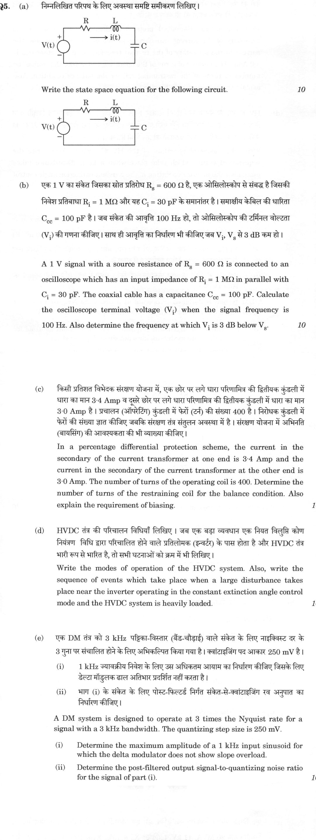
(a) Write the state space equation for the following circuit. [Circuit diagram: voltage source V(t), series resistance R and…
Write the state space equation for the following circuit. [Circuit diagram: voltage source V(t), series resistance R and inductance L, current i(t), and capacitor C] 10 marks
A 1 V signal with a source resistance of R_s = 600 Ω is connected to an oscilloscope which has an input impedance of R_i = 1 MΩ in parallel with C_i = 30 pF. The coaxial cable has a capacitance C_cc = 100 pF. Calculate the oscilloscope terminal voltage (V_i) when the signal frequency is 100 Hz. Also determine the frequency at which V_i is 3 dB below V_s. 10 marks
In a percentage differential protection scheme, the current in the secondary of the current transformer at one end is 3·4 Amp and the current in the secondary of the current transformer at the other end is 3·0 Amp. The number of turns of the operating coil is 400. Determine the number of turns of the restraining coil for the balance condition. Also explain the requirement of biasing. 10 marks
Write the modes of operation of the HVDC system. Also, write the sequence of events which take place when a large disturbance takes place near the inverter operating in the constant extinction angle control mode and the HVDC system is heavily loaded. 10 marks
A DM system is designed to operate at 3 times the Nyquist rate for a signal with a 3 kHz bandwidth. The quantizing step size is 250 mV. Determine the maximum amplitude of a 1 kHz input sinusoid for which the delta modulator does not show slope overload.
Determine the post-filtered output signal-to-quantizing noise ratio for the signal of part (i). 10 marks
हिंदी में प्रश्न पढ़ें
निम्नलिखित परिपथ के लिए अवस्था समष्टि समीकरण लिखिए। [परिपथ आरेख: वोल्टता स्रोत V(t), श्रेणीक्रम में प्रतिरोध R तथा प्रेरकत्व L, धारा i(t), और संधारित्र C] (10 अंक)
एक 1 V का संकेत जिसका स्रोत प्रतिरोध R_s = 600 Ω है, एक ऑसिलोस्कोप से संबद्ध है जिसकी निवेश प्रतिबाधा R_i = 1 MΩ और यह C_i = 30 pF के समानांतर है। समाक्षीय केबिल की धारिता C_cc = 100 pF है। जब संकेत की आवृत्ति 100 Hz हो, तो ऑसिलोस्कोप की टर्मिनल वोल्टता (V_i) की गणना कीजिए। साथ ही आवृत्ति का निर्धारण भी कीजिए जब V_i, V_s से 3 dB कम हो। (10 अंक)
किसी प्रतिशत विभेदक संरक्षण योजना में, एक छोर पर लगे धारा परिणामित्र की द्वितीयक कुंडली में धारा का मान 3·4 Amp व दूसरे छोर पर लगे धारा परिणामित्र की द्वितीयक कुंडली में धारा का मान 3·0 Amp है । प्रचालन (ऑपरेटिंग) कुंडली में फेरों (टर्न) की संख्या 400 है । निरोधक कुंडली में फेरों की संख्या ज्ञात कीजिए जबकि संरक्षण तंत्र संतुलन अवस्था में है । संरक्षण योजना में अभिनति (बायसिंग) की आवश्यकता की भी व्याख्या कीजिए । (10 अंक)
HVDC तंत्र की परिचालन विधियाँ लिखिए । जब एक बड़ा व्यवधान एक नियत विलुप्ति कोण नियंत्रण विधि द्वारा परिचालित होने वाले प्रतिलोमक (इन्वर्टर) के पास होता है और HVDC तंत्र भारी रूप से भारित है, तो सभी घटनाओं को क्रम में भी लिखिए । (10 अंक)
एक DM तंत्र को 3 kHz पट्टिका-विस्तार (बैंड-चौड़ाई) वाले संकेत के लिए नाइक्विस्ट दर के 3 गुना पर संचालित होने के लिए अभिकल्पित किया गया है । क्वांटाइज़िंग पद आकार 250 mV है । 1 kHz ज्यावक्रीय निवेश के लिए उस अधिकतम आयाम का निधार्ण कीजिए जिसके लिए डेल्टा मॉडुलक ढाल अतिभार प्रदर्शित नहीं करता है ।
भाग (i) के संकेत के लिए पोस्ट-फिल्टर्ड निर्गत संकेत-से-क्वांटाइज़िंग रव अनुपात का निधार्ण कीजिए । (10 अंक)
Model answer
Drafted with AI by UPSC Answer Check against this question's marking rubric, to the expected length. UPSC does not publish answers for Mains — this is one way to score well, not an official key. How we build rubrics and answers.
(a) State-space model of the series R-L-C circuit (10 marks)
The circuit has two independent energy stores, so it needs two state variables: the capacitor voltage v_C and the inductor current i (the same current flows through R, L and C). Take x₁ = v_C, x₂ = i and the input u = V(t).
Capacitor. i = C dv_C/dt, so ẋ₁ = (1/C) x₂.
KVL around the loop. V(t) = R i + L di/dt + v_C, so ẋ₂ = −(1/L) x₁ − (R/L) x₂ + (1/L) u.
In standard form ẋ = Ax + Bu:
[ẋ₁; ẋ₂] = [[0, 1/C], [−1/L, −R/L]] [x₁; x₂] + [0; 1/L] V(t).
Taking the capacitor voltage as output, y = v_C = [1 0] x, that is, C = [1 0] and D = 0.
Check. det(sI − A) = s² + (R/L)s + 1/(LC), the characteristic equation of the series RLC circuit, with ω_n = 1/√(LC) and ζ = (R/2)√(C/L).
(b) Oscilloscope terminal voltage and 3 dB frequency (10 marks)
Equivalent circuit. The source (1 V behind R_s = 600 Ω) drives the parallel combination of R_i = 1 MΩ and the total shunt capacitance C = C_i + C_cc = 30 + 100 = 130 pF.
Transfer function. With Z_in = R_i/(1 + jωR_iC),
V_i/V_s = Z_in/(R_s + Z_in) = [R_i/(R_i + R_s)] / [1 + jω(R_s ∥ R_i)C].
The low-frequency divider ratio is R_i/(R_i + R_s) = 10⁶/(10⁶ + 600) = 0.9994. The time constant uses R_s ∥ R_i = 599.64 Ω, so τ = 599.64 × 130 × 10⁻¹² = 7.80 × 10⁻⁸ s and the corner frequency is f_c = 1/(2πτ) = 2.04 MHz.
At 100 Hz. ωτ = 2π × 100 × 7.80 × 10⁻⁸ = 4.9 × 10⁻⁵, which is negligible, so
|V_i| = 0.9994/√(1 + (4.9 × 10⁻⁵)²) ≈ 0.9994 V ≈ 1 V, with a phase lag of only 0.003°. The capacitance has no effect at this frequency.
3 dB frequency. The output falls 3 dB below its low-frequency value at f = f_c = 1/(2πτ) ≈ 2.04 MHz. Measured strictly against 1 V, the 3 dB level is |V_i/V_s| = 0.708, which is reached at f = f_c√[(0.9994/0.708)² − 1] ≈ 2.03 MHz; the two values agree because the divider loss of 0.005 dB is negligible. The scope's bandwidth is limited by the source resistance and the cable plus input capacitance.
(c) Percentage differential relay: restraining-coil turns and the need for biasing (10 marks)
Turns for balance. The operating coil carries the difference of the two CT secondary currents, I₁ − I₂ = 3.4 − 3.0 = 0.4 A. The restraining coil, connected across the two secondaries with its mid-point tapped, carries the through (mean) current (I₁ + I₂)/2 = (3.4 + 3.0)/2 = 3.2 A. At the balance condition the operating and restraining ampere-turns are equal:
N_op (I₁ − I₂) = N_r (I₁ + I₂)/2
400 × 0.4 = N_r × 3.2, so N_r = 50 turns.
The relay therefore operates when the differential current exceeds N_r/N_op = 50/400 = 12.5% of the mean through current.
Why biasing is needed. An unbiased differential relay has a fixed pick-up. In the healthy state, or for a fault outside the protected zone (a through-fault), the CT secondary currents should be equal, but they are not: the CT ratios differ slightly, the magnetising currents differ, a tap changer alters the ratio, and the CTs may saturate unequally when the through current is heavy. The resulting spurious differential current is small at low current but grows with the through current. A fixed low setting would then trip wrongly on external faults, and raising the setting to avoid this would make the relay insensitive to internal faults of low current. Biasing (restraint) solves this: the restraining torque is proportional to the through current, so the pick-up rises automatically with the through current. The relay is stable for heavy through-faults and remains sensitive for internal faults, where the restraint is small and the differential current is large.
(d) HVDC modes of operation and sequence of events after a disturbance near the inverter (10 marks)
Modes of operation. An HVDC link can operate in:
- Monopolar mode: one conductor at one polarity with earth return (or a metallic return conductor).
- Bipolar mode: two poles of opposite polarity, each with its own converter; normally the current in the earth is nearly zero, and either pole can continue alone as monopolar during an outage.
- Homopolar mode: two (or more) conductors of the same polarity, with earth or a metallic return.
In normal operation, the rectifier keeps constant current (CC control) and the inverter holds a constant extinction angle (CEA control), and a voltage-dependent current-order limiter (VDCOL) reduces the current order when the dc voltage falls.
Sequence of events for a large disturbance near an inverter on CEA control, on a heavily loaded link:
- The ac voltage at the inverter bus drops, so the commutating voltage falls.
- The inverter dc voltage V_di = (3√2/π)E cos γ − (3/π)X_c I_d falls, while the rectifier voltage is unchanged, so the dc current I_d rises sharply.
- The larger current and the lower voltage increase the overlap angle μ, so the extinction angle γ = β − μ falls below its set value.
- The CEA controller advances the firing (increases β) to restore γ, but it acts only after a delay of a fraction of a cycle to a cycle.
- If γ falls below the valve turn-off angle γ_min (typically about 15°), the outgoing valve is not turned off in time, and commutation failure occurs.
- The bridge is short-circuited, so the inverter dc voltage collapses towards zero, the dc current surges, and the ac power delivered falls to zero; the rectifier CC control and VDCOL respond by reducing the current order.
- When the disturbance clears and the ac voltage recovers, commutation succeeds and the link recovers within a few cycles, if the failure is not repeated; repeated commutation failures cause the bridge to be blocked and bypassed.
(e) Delta modulator: slope overload and output SQNR (10 marks)
The signal bandwidth is W = 3 kHz, so the Nyquist rate is 2W = 6 kHz and the sampling rate is f_s = 3 × 6 = 18 kHz. The step size is Δ = 0.25 V.
(e)(i) Largest amplitude without slope overload. The maximum slope the modulator can follow is Δf_s = 0.25 × 18000 = 4500 V/s. The maximum slope of A sin(2πf_m t) is 2πf_mA, so for no slope overload 2πf_mA ≤ Δf_s:
A_max = Δf_s/(2πf_m) = 4500/(2π × 1000) = 0.716 V.
(e)(ii) Output SQNR. The signal power is S = A²/2 = 0.716²/2 = 0.2565 W (normalised to 1 Ω). The quantizing noise power, uniformly spread over the range 0 to f_s, is Δ²/3, and the low-pass filter of bandwidth W passes only the fraction W/f_s of it:
N = (Δ²/3)(W/f_s) = (0.0625/3)(3000/18000) = 3.47 × 10⁻³ W.
SQNR = S/N = 0.2565/0.003472 = 73.9, which is 18.7 dB.
(The same result comes from SQNR = 3f_s³/(8π²f_m²W).)
How this answer will be evaluated
Evaluation rubric
Each sub-part is marked on its own, against the marks and word limit printed on the paper.
- (a) For the series R-L-C circuit driven by V(t), choose state variables, apply KVL and the capacitor relation, and write the state-space model ẋ = Ax + Bu (with the output equation if v_C is the output). 10 marks
Must cover
- State variables v_C and i (two energy stores)
- Capacitor relation C dv_C/dt = i and KVL V = Ri + L di/dt + v_C
- Matrix form A = [[0, 1/C], [−1/L, −R/L]], B = [0, 1/L]ᵀ
- Output y = [1 0]x with D = 0
Loses marks
- Choosing charge or flux as states without correct matrices.
- Interchanging the rows or the 1/C and 1/L terms.
- Ignoring the input matrix B.
Earns more
- Correct signs and placement of every matrix element.
- Verification through det(sI − A) = s² + (R/L)s + 1/(LC).
Extra mark
- Identification of ω_n = 1/√(LC) and ζ = (R/2)√(C/L)
- (b) (a) Oscilloscope terminal voltage V_i at 100 Hz for 1 V, R_s = 600 Ω, R_i = 1 MΩ ∥ (C_i + C_cc); (b) frequency at which V_i is 3 dB below V_s. 10 marks
Must cover
- Total shunt capacitance 30 + 100 = 130 pF in parallel with 1 MΩ
- V_i/V_s = [R_i/(R_i + R_s)]/[1 + jω(R_s ∥ R_i)C], with τ ≈ 7.8 × 10⁻⁸ s
- V_i at 100 Hz ≈ 0.9994 V ≈ 1 V (ωτ negligible)
- 3 dB frequency f = 1/(2πτ) ≈ 2.04 MHz
Loses marks
- Omitting the cable capacitance or the input capacitance.
- Treating R_s as 0, which removes the frequency limit.
- Giving the 3 dB frequency as a value in kHz or Hz from an arithmetic slip.
Earns more
- Use of Thévenin or divider form with the source resistance included.
- Comment that the divider loss (0.005 dB) is negligible.
Extra mark
- Phase lag at 100 Hz ≈ 0.003°
- (c) Percentage differential relay: find the restraining-coil turns for balance with CT secondary currents 3.4 A and 3.0 A and an operating coil of 400 turns; explain why biasing is needed. 10 marks
Must cover
- Operating current 0.4 A (difference) and restraining current 3.2 A (mean)
- Balance N_op(I₁ − I₂) = N_r(I₁ + I₂)/2 giving N_r = 50 turns
- Biasing needed because CT ratio errors, saturation and tap changes give spurious differential current on through-faults
- Restraint proportional to through current makes the pick-up rise with current, keeping stability and sensitivity
Loses marks
- Using the sum I₁ + I₂ for the operating coil.
- Omitting the factor of 2 (giving 25 turns or 100 turns).
- Saying biasing is needed only for sensitivity.
Earns more
- Expression of the bias as 12.5% (N_r/N_op).
- Discussion of stability for external faults versus sensitivity for internal faults.
Extra mark
- Mention of inrush current or unequal CT saturation as further reasons
- (d) List the modes of operation of an HVDC system, then set out, in order, the events after a large disturbance near an inverter under CEA control on a heavily loaded link. 10 marks
Must cover
- Modes: monopolar (earth or metallic return), bipolar, homopolar
- Normal control: CC at rectifier, CEA at inverter, VDCOL
- Chronology: ac voltage dip, inverter dc voltage falls and I_d rises, overlap increases and γ falls
- Commutation failure when γ < γ_min, bridge short-circuit, dc voltage collapse, current surge, VDCOL and CC action, then recovery or blocking
Loses marks
- Events listed out of order, for example commutation failure before the voltage dip.
- Confusing rectifier and inverter roles.
- Omitting commutation failure entirely.
Earns more
- Events given in correct causal order.
- Use of V_di and γ = β − μ to justify each step.
Extra mark
- Mention of repeated commutation failures and blocking/bypass
- (e) Delta modulator at 3 times the Nyquist rate of a 3 kHz signal with Δ = 250 mV: (i) largest 1 kHz amplitude with no slope overload; (ii) post-filtered SQNR. 10 marks
Must cover
- f_s = 3 × 6 kHz = 18 kHz
- A_max = Δf_s/(2πf_m) ≈ 0.716 V
- Noise power (Δ²/3)(W/f_s) ≈ 3.47 × 10⁻³ W, signal power A²/2 ≈ 0.2565
- SQNR ≈ 73.9, i.e. 18.7 dB
Loses marks
- Taking f_s = 6 kHz.
- Using noise power Δ²/3 without the W/f_s factor.
- Reporting SQNR only as a ratio or only in dB without the other.
Earns more
- Correct slope condition 2πf_mA ≤ Δf_s.
- Use of the filter bandwidth W = 3 kHz for the noise.
Extra mark
- Cross-check with 3f_s³/(8π²f_m²W)
What "State" is asking you to do
Give the formulation itself — the theorem, rule, statutory provision or position — worded accurately. Precision of wording is the whole of the mark; no background or justification is being asked for.
Structure that answers it
The statement in full, complete in itself → the conditions under which it holds → an illustration only where the stem asks for one
Where marks are lost
Approximating the wording. A theorem or a provision stated loosely forfeits the mark that exact statement would have carried.
Practice this exact question
Write your answer and it is marked point by point against the model answer above — what you covered, what you missed, what you got wrong.
Evaluate my answer →More from Electrical Engineering 2026 Paper II
- Q2 (a) Determine the response of the system shown in the following figure when it is excited…
- Q3 (a) (i) A system has a unit response as c(t) = 1 − e^(−0·5t). Evaluate its unit impulse a…
- Q4 (a) Design a PI controller so that a unity feedback system having open loop transfer func…
- Q5 (a) Write the state space equation for the following circuit. [Circuit diagram: voltage s…
- Q6 (a) Determine the efficiency of a 400 km long transmission line delivering 100 MW load at…
- Q7 (a) A 3-phase line is terminated by a star-connected resistive load of 800 ohm per phase.…
- Q8 (a) A hollow cylinder made of insulating material surrounded by a thin metal sheath has i…