Paper II — Q3
(a) (i) A system has a unit response as c(t) = 1 − e^(−0·5t). Evaluate its unit impulse and unit ramp response, assuming zero…
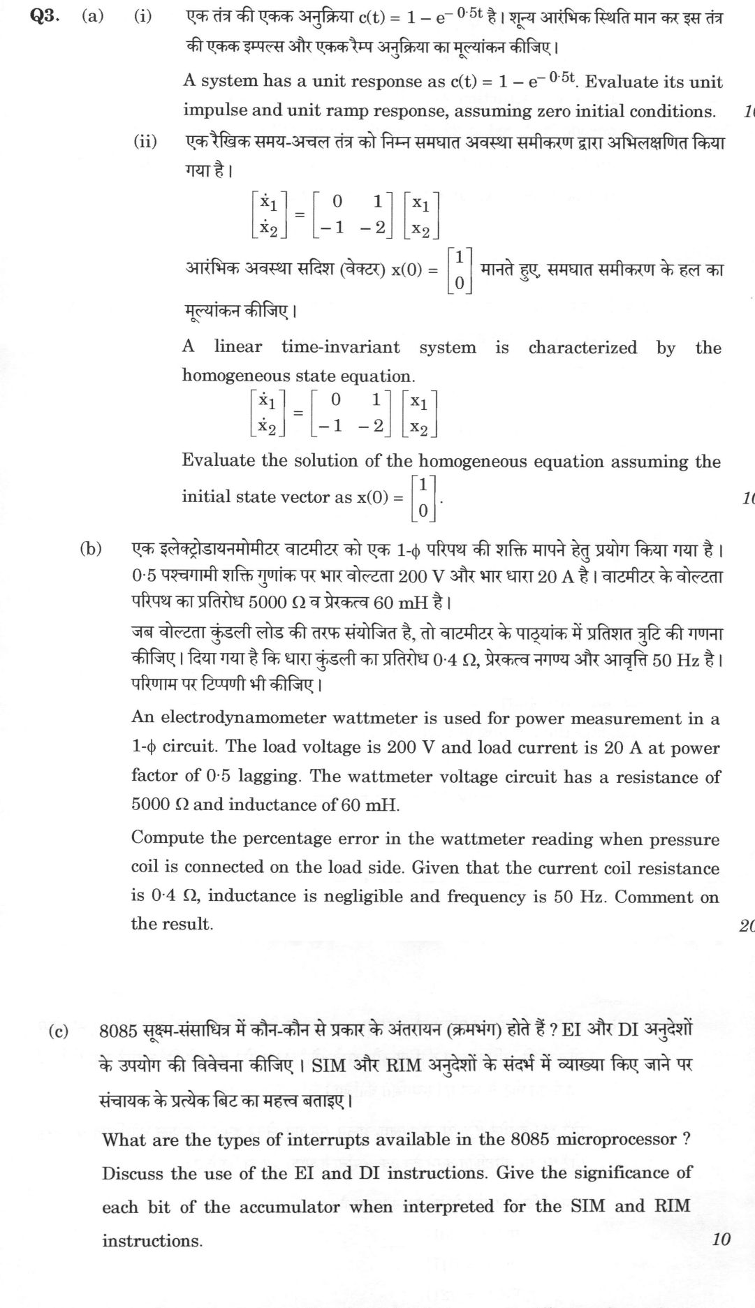
A system has a unit response as c(t) = 1 − e^(−0·5t). Evaluate its unit impulse and unit ramp response, assuming zero initial conditions. 10 marks
A linear time-invariant system is characterized by the homogeneous state equation. [ẋ1; ẋ2] = [0 1; −1 −2] [x1; x2] Evaluate the solution of the homogeneous equation assuming the initial state vector as x(0) = [1; 0]. 10 marks
An electrodynamometer wattmeter is used for power measurement in a 1-φ circuit. The load voltage is 200 V and load current is 20 A at power factor of 0·5 lagging. The wattmeter voltage circuit has a resistance of 5000 Ω and inductance of 60 mH. Compute the percentage error in the wattmeter reading when pressure coil is connected on the load side. Given that the current coil resistance is 0·4 Ω, inductance is negligible and frequency is 50 Hz. Comment on the result. 20 marks
What are the types of interrupts available in the 8085 microprocessor ? Discuss the use of the EI and DI instructions. Give the significance of each bit of the accumulator when interpreted for the SIM and RIM instructions. 10 marks
हिंदी में प्रश्न पढ़ें
एक तंत्र की एकक अनुक्रिया c(t) = 1 − e^(−0·5t) है। शून्य आरंभिक स्थिति मान कर इस तंत्र की एकक इम्पल्स और एकक रैम्प अनुक्रिया का मूल्यांकन कीजिए। (10 अंक)
एक रैखिक समय-अचल तंत्र को निम्न समघात अवस्था समीकरण द्वारा अभिलक्षित किया गया है। [ẋ1; ẋ2] = [0 1; −1 −2] [x1; x2] आरंभिक अवस्था सदिश (वेक्टर) x(0) = [1; 0] मानते हुए, समघात समीकरण के हल का मूल्यांकन कीजिए। (10 अंक)
एक इलेक्ट्रोडायनमोमीटर वाटमीटर को एक 1-φ परिपथ की शक्ति मापने हेतु प्रयोग किया गया है। 0·5 पश्चगामी शक्ति गुणांक पर भार वोल्टता 200 V और भार धारा 20 A है। वाटमीटर के वोल्टता परिपथ का प्रतिरोध 5000 Ω व प्रेरकत्व 60 mH है। जब वोल्टता कुंडली लोड की तरफ संयोजित है, तो वाटमीटर के पाठ्यांक में प्रतिशत त्रुटि की गणना कीजिए। दिया गया है कि धारा कुंडली का प्रतिरोध 0·4 Ω, प्रेरकत्व नगण्य और आवृत्ति 50 Hz है। परिणाम पर टिप्पणी भी कीजिए। (20 अंक)
8085 सूक्ष्म-संसाधित्र में कौन-कौन से प्रकार के अंतरायन (क्रमभंग) होते हैं ? EI और DI अनुदेशों के उपयोग की विवेचना कीजिए । SIM और RIM अनुदेशों के संदर्भ में व्याख्या किए जाने पर संचायक के प्रत्येक बिट का महत्व बताइए । (10 अंक)
Model answer
Drafted with AI by UPSC Answer Check against this question's marking rubric, to the expected length. UPSC does not publish answers for Mains — this is one way to score well, not an official key. How we build rubrics and answers.
(a)(i) Impulse and ramp response from the step response (10 marks)
The unit-step response is c(t) = 1 − e^(−0.5t), so C(s) = 1/s − 1/(s + 0.5) = 0.5/[s(s + 0.5)]. With R(s) = 1/s the transfer function is
G(s) = C(s)/R(s) = 0.5/(s + 0.5),
a first-order system with time constant T = 2 s and unit dc gain.
Unit impulse response. With R(s) = 1, C(s) = 0.5/(s + 0.5), so
g(t) = 0.5 e^(−0.5t), t ≥ 0 (the derivative of the step response).
Unit ramp response. With R(s) = 1/s², C(s) = 0.5/[s²(s + 0.5)] = 1/s² − 2/s + 2/(s + 0.5), so
c_r(t) = t − 2 + 2e^(−0.5t), t ≥ 0 (the integral of the step response).
Check: c_r(0) = 0 and c_r′(0) = 1 − 1 = 0. For large t the output follows t − 2, lagging the ramp by 2 s (the steady-state error equals the time constant, 2).
(a)(ii) Solution of the homogeneous state equation (10 marks)
The solution is x(t) = e^(At) x(0), where e^(At) = L⁻¹{(sI − A)⁻¹}.
State transition matrix. With A = [[0, 1], [−1, −2]],
sI − A = [[s, −1], [1, s + 2]], det = s(s + 2) + 1 = (s + 1)²,
so the characteristic equation has a repeated root s = −1. Then
(sI − A)⁻¹ = (1/(s + 1)²) [[s + 2, 1], [−1, s]] = [[1/(s + 1) + 1/(s + 1)², 1/(s + 1)²], [−1/(s + 1)², 1/(s + 1) − 1/(s + 1)²]].
Taking the inverse transform (L⁻¹{1/(s + 1)²} = te^(−t)):
e^(At) = e^(−t) [[1 + t, t], [−t, 1 − t]].
(Alternatively, A + I = N with N² = 0, so e^(At) = e^(−t)(I + Nt), which gives the same matrix.)
Solution for x(0) = [1, 0]ᵀ.
x(t) = e^(−t) [[1 + t, t], [−t, 1 − t]] [1, 0]ᵀ = e^(−t) [1 + t, −t]ᵀ,
that is x₁(t) = (1 + t)e^(−t) and x₂(t) = −t e^(−t).
Check: x₁(0) = 1, x₂(0) = 0, and ẋ₁ = e^(−t) − (1 + t)e^(−t) = −te^(−t) = x₂, as required by the first state equation. Both states decay to zero, so the system is asymptotically stable.
(b) Error of an electrodynamometer wattmeter with the pressure coil on the load side (20 marks)
Connection. The pressure coil (PC) is connected directly across the load, so it sees the load voltage V = 200 V, but the current coil (CC) carries the load current and the pressure-coil current together. The true load power is P = VI cos φ = 200 × 20 × 0.5 = 2000 W.
Pressure-coil data. R_p = 5000 Ω, X_p = 2πfL = 2π × 50 × 0.06 = 18.85 Ω. The PC current is I_p = V/|Z_p| = 200/5000.04 = 0.040 A, and it lags the voltage by β = tan⁻¹(X_p/R_p) = tan⁻¹(18.85/5000) = 0.216°.
(1) Error from the pressure-coil inductance. The PC current lags the voltage by β, so the wattmeter responds to the current I at an angle φ − β instead of φ. The reading for the load current alone is
W₁ = V I cos β cos(φ − β) = 200 × 20 × 0.99999 × cos(59.784°) = 2013.0 W.
The error is (2013.0 − 2000)/2000 = +0.65%, given by the factor cos²β(1 + tan φ tan β) = 1.0065, which is large here because tan 60° = 1.73 for a low-pf load.
(2) Error from the pressure-coil loss. Because the CC also carries the PC current, the reading includes the power taken by the pressure circuit, V²/R_p = 200²/5000 = 8 W (more exactly V I_p cos β = 8.0 W). The error from this is 8/2000 = +0.40%.
Total. The wattmeter reading is W = 2013.0 + 8.0 = 2021 W, so the percentage error is
(2021 − 2000)/2000 × 100 = +1.05% (the meter reads high).
Comment. The error is small, about 1%, because the pressure circuit has a high resistance and a small phase angle. It is positive for a lagging load and would be negative for a leading load, and it increases as the power factor falls (through tan φ). It can be removed by subtracting the pressure-coil loss and by compensating the coil inductance, for example with a small capacitor across part of the series resistance. The given current-coil resistance of 0.4 Ω is not part of this connection. If instead the pressure coil were connected on the supply side of the current coil, the voltage across the PC would include the CC drop, and the reading would exceed the load power by the CC loss, I²R_cc = 20² × 0.4 = 160 W, an error of +8%. For a high-current load like this one, the load-side connection is therefore better.
(c) 8085 interrupts, EI/DI and the SIM and RIM words (10 marks)
Types of interrupts. The 8085 has five hardware interrupts and eight software interrupts.
- TRAP (RST 4.5): non-maskable, highest priority, level and edge sensitive, vector 0024H.
- RST 7.5: maskable, rising-edge sensitive (latched), second priority, vector 003CH.
- RST 6.5: maskable, level sensitive, third priority, vector 0034H.
- RST 5.5: maskable, level sensitive, fourth priority, vector 002CH.
- INTR: maskable, level sensitive, lowest priority and non-vectored; the interrupting device supplies an instruction (normally RST n or CALL) after INTA.
- Software interrupts: the instructions RST 0 to RST 7, which branch to 8 × n (0000H, 0008H, …, 0038H). They cannot be masked.
The hardware interrupts other than INTR are vectored. Vectored interrupts jump to a fixed address, and non-vectored ones take the address from the device.
EI and DI. EI (enable interrupts, opcode FBH) sets the interrupt-enable flip-flop; the maskable interrupts (RST 7.5, 6.5, 5.5, INTR) are then recognised after the following instruction has been executed. DI (disable interrupts, opcode F3H) resets the flip-flop and disables all the maskable interrupts; TRAP is unaffected. The flip-flop is also reset by RESET and automatically when an interrupt is accepted. DI is used around critical or time-critical code sections that must not be interrupted, and EI is used to re-enable interrupts, usually just before RET at the end of a service routine so that interrupts can be accepted again once the routine has returned.
SIM (set interrupt mask) – accumulator bits.
- D₀ (M5.5), D₁ (M6.5), D₂ (M7.5): mask bits; 1 masks (disables) the interrupt, and they take effect only if D₃ = 1.
- D₃ (MSE): mask set enable; 1 allows D₀–D₂ to set the masks.
- D₄ (R7.5): reset RST 7.5 flip-flop; 1 clears the latched request.
- D₅: not used.
- D₆ (SOE): serial output enable; 1 lets D₇ appear on SOD.
- D₇ (SOD): serial output data bit sent to the SOD pin.
RIM (read interrupt mask) – accumulator bits after execution.
- D₀ (M5.5), D₁ (M6.5), D₂ (M7.5): current mask status (1 = masked).
- D₃ (IE): interrupt-enable flip-flop status (1 = enabled).
- D₄ (I5.5), D₅ (I6.5), D₆ (I7.5): pending status of the respective interrupts (1 = pending).
- D₇ (SID): serial input data bit read from the SID pin.
How this answer will be evaluated
Evaluation rubric
Each sub-part is marked on its own, against the marks and word limit printed on the paper.
- (a)(i) Given the unit STEP response c(t) = 1 − e^(−0.5t), find (a) the unit impulse response and (b) the unit ramp response, with zero initial conditions. 10 marks
Must cover
- Transfer function G(s) = 0.5/(s + 0.5) from C(s) = 0.5/[s(s + 0.5)] with R(s) = 1/s
- Impulse response g(t) = 0.5e^(−0.5t), t ≥ 0
- Ramp response c_r(t) = t − 2 + 2e^(−0.5t), t ≥ 0, via partial fractions or integrating the step response
- Checks such as c_r(0) = 0, or time constant 2 s and steady-state ramp error 2
Loses marks
- Treating the given c(t) as the impulse or ramp response.
- Sign error giving t + 2 − 2e^(−0.5t).
- Using non-zero initial conditions.
Earns more
- Correct partial-fraction expansion of 0.5/[s²(s + 0.5)].
- Recognising that impulse = derivative and ramp = integral of the step response.
Extra mark
- Remark that the ramp output lags the input by the time constant, 2 s
- (a)(ii) Solve ẋ = Ax with A = [[0, 1], [−1, −2]] and x(0) = [1, 0]ᵀ: find e^(At) and hence x₁(t) and x₂(t). 10 marks
Must cover
- (sI − A) and its determinant (s + 1)², repeated eigenvalue −1
- (sI − A)⁻¹ = [[s + 2, 1], [−1, s]]/(s + 1)²
- State transition matrix e^(At) = e^(−t)[[1 + t, t], [−t, 1 − t]]
- x₁(t) = (1 + t)e^(−t) and x₂(t) = −te^(−t)
Loses marks
- Treating the repeated pole as two distinct exponentials.
- Wrong matrix entries, for example the sign of the off-diagonal terms.
- Computing e^(At) element-wise as e^(a_ij t).
Earns more
- Correct inverse Laplace transforms including te^(−t) for the repeated pole.
- Verification that ẋ₁ = x₂ and the initial conditions hold.
Extra mark
- Alternative derivation e^(At) = e^(−t)(I + Nt) with N = A + I, N² = 0
- Comment that the system is asymptotically stable
- (b) For an electrodynamometer wattmeter with the pressure coil on the load side (V = 200 V, I = 20 A, pf 0.5 lag, R_p = 5000 Ω, L_p = 60 mH, R_cc = 0.4 Ω, 50 Hz): find the percentage error from (a) the pressure-coil inductance and (b) the pressure-coil power loss, then comment, including the role of the current-coil resistance in the alternative connection. 20 marks
Must cover
- True power 2000 W; X_p = 18.85 Ω and β = tan⁻¹(X_p/R_p) ≈ 0.216°
- Inductance error from cos²β(1 + tan φ tan β) ≈ 1.0065, about +0.65% (reading ≈ 2013 W)
- Pressure-coil loss V²/R_p = 8 W, about +0.40%
- Total reading ≈ 2021 W, error ≈ +1.05% (reads high for lagging load)
- Comment: error grows with tan φ, sign reverses for leading load, compensation possible; the 0.4 Ω CC resistance matters for the supply-side connection (I²R = 160 W, +8%)
Loses marks
- Applying the CC resistance loss (160 W) to the load-side connection.
- Taking β as 0 and reporting no inductance error.
- Wrong sign, that is, reporting the wattmeter as reading low for a lagging load.
Earns more
- Correct treatment of PC current lagging the voltage by β so that the current is seen at angle φ − β.
- Numerical steps shown for each of the two errors and the total.
Extra mark
- Suggesting a compensating capacitor across the series resistor, or a compensated wattmeter
- (c) Three demands: classify the 8085 interrupts (hardware/software, vectored/non-vectored, maskable/non-maskable, with priorities and vector addresses); explain the use of EI and DI; and give the bit-by-bit meaning of the accumulator for SIM and for RIM. 10 marks
Must cover
- TRAP 0024H (non-maskable, highest), RST 7.5 003CH, RST 6.5 0034H, RST 5.5 002CH, INTR (non-vectored, lowest); software RST 0–7 at 8n
- EI (FBH) enables and DI (F3H) disables the maskable interrupts; DI does not affect TRAP; auto-disabled on acceptance and reset
- SIM: D0–D2 mask bits M5.5, M6.5, M7.5, D3 MSE, D4 R7.5 reset, D5 unused, D6 SOE, D7 SOD
- RIM: D0–D2 current masks, D3 IE, D4–D6 pending I5.5, I6.5, I7.5, D7 SID
Loses marks
- Swapping the vector addresses or priority order of RST 5.5, 6.5 and 7.5.
- Stating that DI disables TRAP.
- Mixing up SIM and RIM bit meanings, for example placing SOD or SID at the wrong bit.
Earns more
- Correct edge/level sensitivity of TRAP and RST 7.5, and level sensitivity of RST 6.5, 5.5 and INTR.
- Uses of DI around critical sections and EI before RET in a service routine.
Extra mark
- Noting that INTR supplies RST n or CALL through INTA
What "Evaluate" is asking you to do
Judge how well something has performed against the standard it set for itself — its stated aim, mandate or promise — and commit to a verdict. Name the yardstick before you judge; an unanchored judgement reads as opinion.
Structure that answers it
Name the yardstick — stated aim, mandate or benchmark → performance against it → shortfall against it → why the gap exists → verdict
Where marks are lost
Presenting both sides and then declining to decide, or delivering a verdict against a standard you never stated, which makes it look arbitrary.
Practice this exact question
Write your answer and it is marked point by point against the model answer above — what you covered, what you missed, what you got wrong.
Evaluate my answer →More from Electrical Engineering 2026 Paper II
- Q1 (a) A unity feedback system has open loop transfer function G(s) = \frac{K}{s(s+q)}. Eval…
- Q2 (a) Determine the response of the system shown in the following figure when it is excited…
- Q3 (a) (i) A system has a unit response as c(t) = 1 − e^(−0·5t). Evaluate its unit impulse a…
- Q4 (a) Design a PI controller so that a unity feedback system having open loop transfer func…
- Q5 (a) Write the state space equation for the following circuit. [Circuit diagram: voltage s…
- Q6 (a) Determine the efficiency of a 400 km long transmission line delivering 100 MW load at…