Paper I — Q3
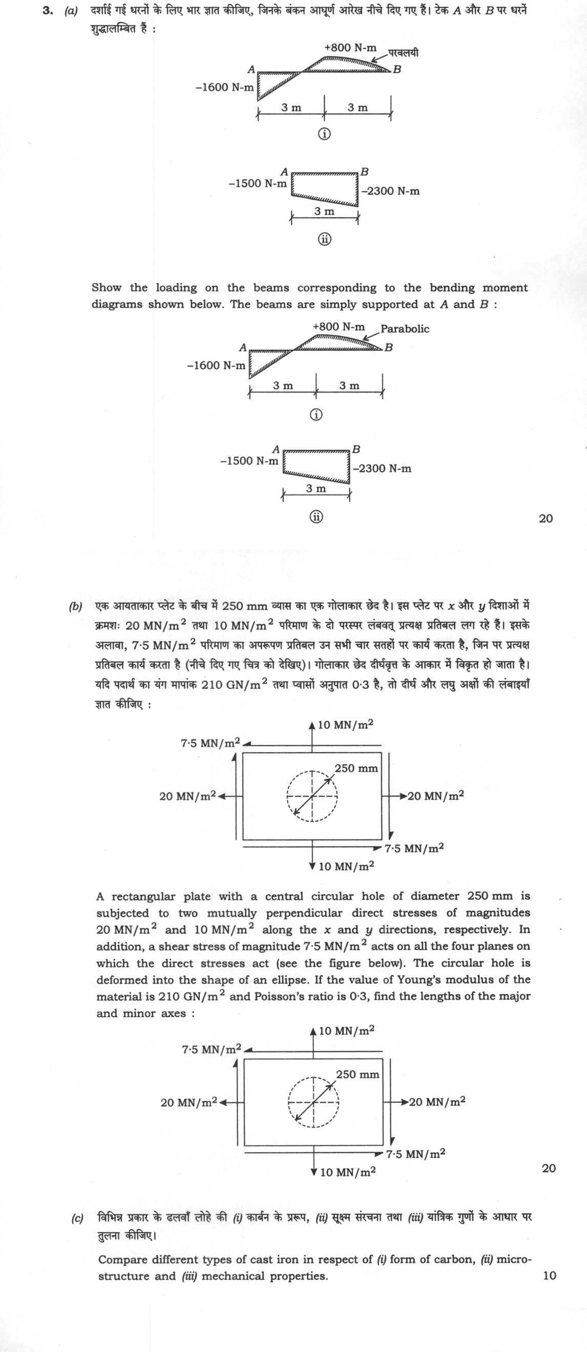
(a) Show the loading on the beams corresponding to the bending moment diagrams shown below. The beams are simply supported at A…
Show the loading on the beams corresponding to the bending moment diagrams shown below. The beams are simply supported at A and B : 20 marks
A rectangular plate with a central circular hole of diameter 250 mm is subjected to two mutually perpendicular direct stresses of magnitudes 20 MN/m² and 10 MN/m² along the x and y directions, respectively. In addition, a shear stress of magnitude 7·5 MN/m² acts on all the four planes on which the direct stresses act (see the figure below). The circular hole is deformed into the shape of an ellipse. If the value of Young's modulus of the material is 210 GN/m² and Poisson's ratio is 0·3, find the lengths of the major and minor axes : 20 marks
Compare different types of cast iron in respect of (i) form of carbon, (ii) micro-structure and (iii) mechanical properties. 10 marks
हिंदी में प्रश्न पढ़ें
दर्शाई गई धरनों के लिए भार ज्ञात कीजिए, जिनके बंकन आधुर्ण आरेख नीचे दिए गए हैं। टेक A और B पर धरने शुडालंबित हैं : (20 अंक)
एक आयताकार प्लेट के बीच में 250 mm व्यास का एक गोलाकार छेद है। इस प्लेट पर x और y दिशाओं में क्रमशः 20 MN/m² तथा 10 MN/m² परिमाण के दो परस्पर लंबवत् प्रत्यक्ष प्रतिबल लग रहे हैं। इसके अलावा, 7·5 MN/m² परिमाण का अपरूपण प्रतिबल उन सभी चार सतहों पर कार्य करता है, जिन पर प्रत्यक्ष प्रतिबल कार्य करता है (नीचे दिए गए चित्र को देखिए)। गोलाकार छेद दीर्घवृत्त के आकार में विकृत हो जाता है। यदि पदार्थ का यंग मापांक 210 GN/m² तथा प्वासों अनुपात 0·3 है, तो दीर्घ और लघु अक्षों की लंबाइयाँ ज्ञात कीजिए : (20 अंक)
विभिन्न प्रकार के ढलवां लोहे की (i) कार्बन के प्ररूप, (ii) सूक्ष्म संरचना तथा (iii) यांत्रिक गुणों के आधार पर तुलना कीजिए। (10 अंक)
The figure this question refers to, in words
The question paper is a scan and the diagram did not survive as text. This is the figure as read from the original page — every component, value and label — so the question can be worked from the text below.
(a) Bending Moment Diagram (ii): A beam of length 3 m with supports at ends A and B. The diagram shows a linear variation (trapezoidal shape) with a value of -1500 N-m at point A and -2300 N-m at point B. The entire diagram lies below the baseline.
(b) A schematic diagram showing a rectangular plate with a central circular hole. The hole has a diameter of 250 mm. The plate is subjected to a state of plane stress. A horizontal tensile stress of 20 MN/m^2 acts on the vertical faces. A vertical tensile stress of 10 MN/m^2 acts on the horizontal faces. A shear stress of 7.5 MN/m^2 acts on the faces, with arrows indicating the direction of shear on the top, bottom, left, and right edges.
What "Solve" is asking you to do
Choose the method, then carry it through to a final answer. Identifying what kind of problem this is and why that method applies is the first thing marked; a correct figure arrived at invisibly earns almost nothing.
Structure that answers it
Given data and what is required → method chosen, with the reason it applies → set-up (equation, circuit, free body, trial balance) → working, step by step → answer with units and any condition of validity
Where marks are lost
Doing the middle steps mentally and writing only the result. In mathematics papers, a further loss comes from giving a decimal where the exact value in surds or fractions was wanted, or from skipping the justification a part explicitly asks for.
How this answer will be evaluated
Approach
(a) calculate: given > formula > substitution > result with units > interpretation | (b) calculate: given > formula > substitution > result with units > interpretation | (c) compare: paired headings or table > key differences > significance > conclusion Full marks: Rigorous derivation of loads from BMD; precise calculation of principal strains and dimensions; comprehensive and accurate comparison of cast irons.
Key points expected
- Identify support reactions from BMD end values
- Deduce point loads from BMD slope changes
- Deduce distributed loads from BMD curvature
- Draw the corresponding free body diagram
- Calculate principal stresses using Mohr's circle or formula
- Determine principal strains using generalized Hooke's law
- Relate principal strains to the change in hole dimensions
- Compute final major and minor axis lengths
Evaluation rubric
Each sub-part is marked on its own, against the marks and word limit printed on the paper.
- (a) Determine the loading (forces and moments) on the beams corresponding to the given BMDs. 20 marks
calculate— given → formula → substitution → result with units → interpretation
Must cover
- Identify support reactions from BMD end values
- Deduce point loads from BMD slope changes
- Deduce distributed loads from BMD curvature
- Draw the corresponding free body diagram
Loses marks
- Assuming loads without deriving from BMD features
- Ignoring the sign convention of the BMD
- Failing to distinguish between point and distributed loads
Earns more
- Explicitly state the relationship dM/dx = V
- Verify equilibrium of the derived loads
- Label all forces and dimensions clearly
Extra mark
- Show the shear force diagram (SFD) as an intermediate step
- (b) Calculate the lengths of the major and minor axes of the deformed hole. 20 marks
calculate— given → formula → substitution → result with units → interpretation
Must cover
- Calculate principal stresses using Mohr's circle or formula
- Determine principal strains using generalized Hooke's law
- Relate principal strains to the change in hole dimensions
- Compute final major and minor axis lengths
Loses marks
- Confusing principal stresses with maximum shear stresses
- Using the wrong sign for Poisson's ratio terms
- Failing to convert units consistently (MN/m² to GN/m²)
Earns more
- Correctly identify the orientation of principal stresses
- Show the calculation of shear strain if applicable
- State the assumption of plane stress
Extra mark
- Sketch the deformed ellipse with labeled axes
- (c) Compare different types of cast iron based on carbon form, microstructure, and properties. 10 marks
compare— paired headings or table → key differences → significance → conclusion
Must cover
- Identify at least three types of cast iron (e.g., Grey, White, Malleable)
- Describe the form of carbon for each type
- Describe the microstructure for each type
- Compare mechanical properties (strength, ductility, hardness)
Loses marks
- Listing types without comparing them
- Confusing the microstructure of grey and white iron
- Failing to link microstructure to mechanical properties
Earns more
- Use a table format for clear comparison
- Mention specific applications for each type
- Explain the effect of cooling rate on microstructure
Extra mark
- Include a diagram of the microstructure for one type
Model answer coming soon
Every evaluation on this site is marked against a verified model answer. This question's answer is still being written; evaluation opens the moment it lands.
More from Mechanical Engineering 2024 Paper I
- Q1 (a) A rod of length 2 m and weight 450 N rests on ground at one end. The other end is sup…
- Q2 (a) Bodies A, B and C of weights 100 N, 200 N and 150 N, respectively are connected as sh…
- Q3 (a) Show the loading on the beams corresponding to the bending moment diagrams shown belo…
- Q4 (a) A governor of Hartnell type has each ball of weight 20 N and the lengths of vertical…
- Q5 (a) A cutting tool is used to machine alloy steel at cutting speed of 40 m/min. Consideri…
- Q6 (a) A perfectly plastic material having yield strength of 300 MPa is subjected to extrusi…