Paper I — Q1
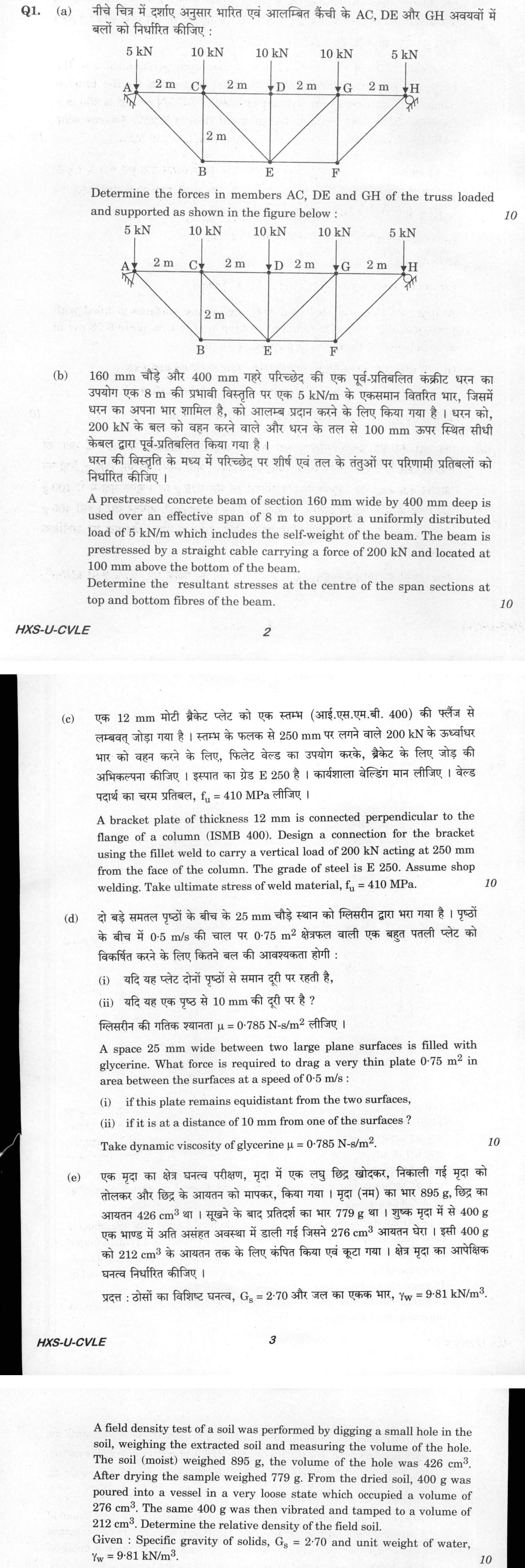
(a) Determine the forces in members AC, DE and GH of the truss loaded and supported as shown in the figure below : (10…
Determine the forces in members AC, DE and GH of the truss loaded and supported as shown in the figure below : 10 marks
A prestressed concrete beam of section 160 mm wide by 400 mm deep is used over an effective span of 8 m to support a uniformly distributed load of 5 kN/m which includes the self-weight of the beam. The beam is prestressed by a straight cable carrying a force of 200 kN and located at 100 mm above the bottom of the beam. Determine the resultant stresses at the centre of the span sections at top and bottom fibres of the beam. 10 marks
A bracket plate of thickness 12 mm is connected perpendicular to the flange of a column (ISMB 400). Design a connection for the bracket using the fillet weld to carry a vertical load of 200 kN acting at 250 mm from the face of the column. The grade of steel is E 250. Assume shop welding. Take ultimate stress of weld material, f_u = 410 MPa. 10 marks
A space 25 mm wide between two large plane surfaces is filled with glycerine. What force is required to drag a very thin plate 0·75 m² in area between the surfaces at a speed of 0·5 m/s : (i) if this plate remains equidistant from the two surfaces, (ii) if it is at a distance of 10 mm from one of the surfaces ? Take dynamic viscosity of glycerine μ = 0·785 N-s/m². 10 marks
A field density test of a soil was performed by digging a small hole in the soil, weighing the extracted soil and measuring the volume of the hole. The soil (moist) weighed 895 g, the volume of the hole was 426 cm³. After drying the sample weighed 779 g. From the dried soil, 400 g was poured into a vessel in a very loose state which occupied a volume of 276 cm³. The same 400 g was then vibrated and tamped to a volume of 212 cm³. Determine the relative density of the field soil. Given : Specific gravity of solids, G_S = 2·70 and unit weight of water, γ_w = 9·81 kN/m³. 10 marks
हिंदी में प्रश्न पढ़ें
नीचे चित्र में दर्शाए अनुसार भारित एवं आलंबित कैंची के AC, DE और GH अवयवों में बलों को निर्धारित कीजिए : (10 अंक)
160 mm चौड़े और 400 mm गहरे परिछेद की एक पूर्व-प्रतिबलित कंक्रीट धरन का उपयोग एक 8 m की प्रभावी विस्तृति पर एक 5 kN/m के एकसमान वितरित भार, जिसमें धरन का अपना भार शामिल है, को आलंब प्रदान करने के लिए किया गया है । धरन को, 200 kN के बल को वहन करने वाले और धरन के तल से 100 mm ऊपर स्थित सीधी केबल द्वारा पूर्व-प्रतिबलित किया गया है । धरन की विस्तृति के मध्य में परिछेद पर शीर्ष एवं तल के तंतुओं पर परिणामी प्रतिबलों को निर्धारित कीजिए । (10 अंक)
एक 12 mm मोटी ब्रैकेट प्लेट को एक स्तम्भ (आई.एस.एम.बी. 400) की फ्लैंज से लम्बवत् जोड़ा गया है । स्तम्भ के फलक से 250 mm पर लगने वाले 200 kN के उद्वधर भार को वहन करने के लिए, फिलेट वेल्ड का उपयोग करके, ब्रैकेट के लिए जोड़ की अभिकल्पना कीजिए । इसपात का ग्रेड E 250 है । कार्यशाला वेल्डिंग मान लीजिए । वेल्ड पदार्थ का चरम प्रतिबल, f_u = 410 MPa लीजिए । (10 अंक)
दो बड़े समतल पृष्ठों के बीच के 25 mm चौड़े स्थान को ग्लिसरिन द्वारा भरा गया है । पृष्ठों के बीच में 0·5 m/s की चाल पर 0·75 m² क्षेत्रफल वाली एक बहुत पतली प्लेट को विचलित करने के लिए कितने बल की आवश्यकता होगी : (i) यदि यह प्लेट दोनों पृष्ठों से समान दूरी पर रहती है, (ii) यदि यह एक पृष्ठ से 10 mm की दूरी पर है ? ग्लिसरिन की गतिक श्यानता μ = 0·785 N-s/m² लीजिए । (10 अंक)
एक मृदा का क्षेत्र घनत्व परीक्षण, मृदा में एक लघु छिद्र खोदकर, निकाली गई मृदा को तौलकर और छिद्र के आयतन को मापकर, किया गया । मृदा (नम) का भार 895 g, छिद्र का आयतन 426 cm³ था । सूखने के बाद प्रतिदर्श का भार 779 g था । शुष्क मृदा में से 400 g एक भांड़ में अति असंत अवस्था में डाली गई जिसमें 276 cm³ आयतन घेरा । इसी 400 g को 212 cm³ के आयतन तक के लिए कंपित किया एवं कुटा गया । क्षेत्र मृदा का आपेक्षिक घनत्व निर्धारित कीजिए । प्रदत : ठोसों का विशिष्ट घनत्व, G_s = 2·70 और जल का एकक भार, γ_w = 9·81 kN/m³. (10 अंक)
The figure this question refers to, in words
The question paper is a scan and the diagram did not survive as text. This is the figure as read from the original page — every component, value and label — so the question can be worked from the text below.
(a) A planar truss structure with top chord nodes A, C, D, G, H and bottom chord nodes B, E, F. The horizontal distance between adjacent top nodes (A-C, C-D, D-G, G-H) is 2 m each. The vertical distance between the top chord and bottom chord is 2 m. The bottom chord consists of members BE and EF, each 2 m long. Diagonal members connect A to B, C to B, C to E, E to G, and F to H. Vertical members connect C to B, D to E, and G to F. The truss is supported by a pin support at node A and a roller support at node H. Downward vertical point loads are applied at the top nodes: 5 kN at A, 10 kN at C, 10 kN at D, 10 kN at G, and 5 kN at H.
(b) A cross-sectional view of a T-beam. The top flange has a width of 1000 mm and a thickness of 100 mm. The vertical web has a width of 300 mm and a depth of 400 mm. The total depth of the beam is 500 mm. At the bottom of the web, there are 4 reinforcing bars, each with a diameter of 25 mm (labeled '25 phi ki 4 chode' in Hindi and '4 nos 25 phi bar' in English). The center of these bars is located 50 mm from the bottom edge of the beam. The text below the figure specifies: 'M 20 grade of concrete and Fe 415 HYSD bars'.
(c) A horizontal bar ABCD is fixed at both ends A and D. The bar consists of three segments: AB, BC, and CD. Segment AB has a length of 300 mm. Segment BC has a length of 500 mm. Segment CD has a length of 300 mm. An axial load P_B is applied at point B, directed to the right. An axial load P_C is applied at point C, directed to the left. The labels A, B, C, and D mark the joints and supports along the bar.
A cross-sectional view of a gravity retaining wall. The wall is a trapezoidal concrete structure with a vertical back face and a sloping front face. The total height of the wall is 6 m. The top width of the wall is 1 m. The bottom width of the wall is 3 m. The unit weight of the concrete is given as gamma_c = 24 kN/m^3. The wall retains a deposit of granular backfill soil on its vertical back face. The soil surface is level with the top of the wall. The soil properties are: unit weight gamma = 17.5 kN/m^3, angle of internal friction phi = 35 degrees, and cohesion C = 0. The base of the wall rests on a foundation soil.
Model answer
Written by UPSC Answer Check against this question's marking rubric, to the expected length. UPSC does not publish answers for Mains — this is one way to score well, not an official key.
(a)
- The truss is planar, statically determinate, and symmetric about midspan. The loading is also symmetric.
- Total vertical load = 5 + 10 + 10 + 10 + 5 = 40 kN.
- Vertical reactions: R_A = R_H = 40/2 = 20 kN upward. No horizontal load, so the horizontal reaction at A is zero.
- Use the method of joints. Take tension as positive. Each diagonal has horizontal and vertical projections of 2 m, so it is at 45° and its vertical and horizontal components are equal to F/√2.
- At joint A, the net external vertical force is 20 - 5 = 15 kN upward.
- Member AC is horizontal; member AB is inclined 45° downward to the right.
- Vertical equilibrium at A: ΣF_y = 15 - F_AB/√2 = 0 F_AB/√2 = 15 kN F_AB = 15√2 kN tension.
- Horizontal equilibrium at A: ΣF_x = F_AC + F_AB/√2 = 0 F_AC + 15 = 0 F_AC = -15 kN.
- The negative sign means compression.
- By symmetry, at joint H the diagonal HF has the same force, F_HF = 15√2 kN tension, and its horizontal component is 15 kN. Horizontal equilibrium gives F_GH = -15 kN, i.e. compression.
- At joint D, the only vertical member is DE. The applied load is 10 kN downward. Taking tension in DE as pulling D downward, ΣF_y = -10 - F_DE = 0 F_DE = -10 kN.
- The negative sign means compression.
- A quick check at joint B shows that the 15 kN horizontal component of AB is balanced by BE in tension, and the 15 kN vertical component is balanced by CB in compression, so the assumed member forces are consistent.
F_AC = 15 kN compression, F_DE = 10 kN compression, F_GH = 15 kN compression.
(b)
- Assume the beam is simply supported, the section is the stated rectangular section, there are no prestress losses, and the behaviour is linear elastic.
- Width b = 160 mm, depth D = 400 mm.
- Area A = bD = 160 × 400 = 64,000 mm².
- Moment of inertia I = bD³/12 = 160 × 400³/12 = 8.5333 × 10⁸ mm⁴.
- Section modulus S = I/(D/2) = bD²/6 = 160 × 400²/6 = 4.2667 × 10⁶ mm³.
- Prestress force P = 200 kN = 2.00 × 10⁵ N.
- The centroid is at 200 mm from the bottom. The cable is at 100 mm from the bottom, so the eccentricity is e = 100 mm below the centroid.
- Use superposition of the axial prestress force and the bending moment caused by its eccentricity. The cable is straight, so this prestress moment is constant along the span.
- Uniform axial stress: P/A = 200,000/64,000 = 25/8 = 3.125 N/mm² compression.
- Bending stress due to eccentricity: Pe/S = 200,000 × 100 / 4.2667 × 10⁶ = 75/16 = 4.6875 N/mm².
- Because the prestressing force is below the centroid, it increases compression at the bottom fibre and reduces compression, or causes tension, at the top fibre.
- Prestress stresses: top: 3.125 - 4.6875 = -1.5625 N/mm², i.e. 1.5625 N/mm² tension. bottom: 3.125 + 4.6875 = 7.8125 N/mm² compression.
- The uniformly distributed load is w = 5 kN/m over an effective span L = 8 m.
- Midspan moment for a simply supported beam: M = wL²/8 = 5 × 8²/8 = 40 kN·m = 4.0 × 10⁷ N·mm.
- Flexural stress: M/S = 4.0 × 10⁷ / 4.2667 × 10⁶ = 75/8 = 9.375 N/mm².
- Sagging moment gives compression at the top fibre and tension at the bottom fibre.
- Superpose the prestress and load stresses: top: -75/16 + 25/8 + 75/8 = 125/16 = 7.8125 N/mm² compression. bottom: 75/16 + 25/8 - 75/8 = -25/16 = -1.5625 N/mm², i.e. 1.5625 N/mm² tension.
- The units N/mm² are equivalent to MPa.
Top fibre stress = 7.8125 MPa compression; bottom fibre stress = 1.5625 MPa tension.
(c)
[(c)] The figure printed on the original question paper for this part could not be recovered from the scan, so this part is not answered here.
(d)
- Use Newton’s law of viscosity: τ = μ du/dy.
- The plate is very thin, so its thickness is neglected. The gaps are small and the velocity profile in each glycerine layer is linear. The outer surfaces are stationary and the plate moves at V = 0.5 m/s.
- For a gap h, du/dy = V/h, so τ = μV/h. The shear force on one face is τA. The two faces act in the same direction to resist the drag, so the total force is F = A μ V (1/h_1 + 1/h_2), where A = 0.75 m² and μ = 0.785 N-s/m².
- No edge effects are considered because the surfaces are large and the plate is thin.
(i)
- The plate is equidistant from the two surfaces, so each gap is h_1 = h_2 = 25/2 = 12.5 mm = 0.0125 m.
- Shear stress on each face: τ = 0.785 × 0.5 / 0.0125 = 31.4 N/m².
- Force on both faces: F = 2 × 31.4 × 0.75 = 47.1 N.
F = 47.1 N.
(ii)
- The plate is 10 mm from one surface, so h_1 = 10 mm = 0.010 m, h_2 = 25 - 10 = 15 mm = 0.015 m.
- Shear stress on the 10 mm gap side: τ_1 = 0.785 × 0.5 / 0.010 = 39.25 N/m².
- Shear stress on the 15 mm gap side: τ_2 = 0.785 × 0.5 / 0.015 = 26.1667 N/m².
- Total force: F = (39.25 + 26.1667) × 0.75 = 49.0625 N.
F = 49.0625 N, approximately 49.1 N.
(e)
- The moisture content is not required for relative density; only the dry densities are needed.
- Field dry density: ρ_d,field = 779/426 = 1.82864 g/cm³.
- Since 1 g/cm³ corresponds to 9.81 kN/m³, γ_d,field = 1.82864 × 9.81 = 17.9389 kN/m³.
- Loose state: 400 g occupies 276 cm³. ρ_d,loose = 400/276 = 1.44928 g/cm³, γ_d,loose = 1.44928 × 9.81 = 14.2174 kN/m³.
- This is the minimum dry density and corresponds to the maximum void ratio e_max.
- Tamped state: 400 g occupies 212 cm³. ρ_d,dense = 400/212 = 1.88679 g/cm³, γ_d,dense = 1.88679 × 9.81 = 18.5094 kN/m³.
- This is the maximum dry density and corresponds to the minimum void ratio e_min.
- Use the void ratio relation for a soil of specific gravity G_S: e = G_S γ_w / γ_d - 1, with G_S = 2.70 and γ_w = 9.81 kN/m³.
- Field void ratio: e_field = 2.70 × 9.81 / 17.9389 - 1 = 0.47651.
- Maximum void ratio: e_max = 2.70 × 9.81 / 14.2174 - 1 = 0.86300.
- Minimum void ratio: e_min = 2.70 × 9.81 / 18.5094 - 1 = 0.43100.
- Relative density: D_r = (e_max - e_field)/(e_max - e_min) × 100 = (0.86300 - 0.47651)/(0.86300 - 0.43100) × 100 = 89.47%.
- The field dry density lies between the loose and dense dry densities, so a relative density between 0 and 100% is expected; the result is consistent.
Relative density of the field soil = 89.5%.
What "Solve" is asking you to do
Choose the method, then carry it through to a final answer. Identifying what kind of problem this is and why that method applies is the first thing marked; a correct figure arrived at invisibly earns almost nothing.
Structure that answers it
Given data and what is required → method chosen, with the reason it applies → set-up (equation, circuit, free body, trial balance) → working, step by step → answer with units and any condition of validity
Where marks are lost
Doing the middle steps mentally and writing only the result. In mathematics papers, a further loss comes from giving a decimal where the exact value in surds or fractions was wanted, or from skipping the justification a part explicitly asks for.
How this answer will be evaluated
Approach
(a) calculate: given > formula > substitution > result with units > interpretation | (b) calculate: given > formula > substitution > result with units > interpretation | (c) justify: claim > 3-4 reasons > evidence > conclusion | (d) calculate: given > formula > substitution > result with units > interpretation | (e) calculate: given > formula > substitution > result with units > interpretation Full marks: Complete working with correct values, units, and clear presentation for all parts.
Key points expected
- Calculate support reactions at A and H
- Apply method of sections or joints
- State magnitude and nature (T/C) for AC, DE, GH
- Carry units (kN) through all steps
- Calculate section properties (A, Z, e)
- Compute bending moment due to UDL
- Apply superposition of P/A, PeZ, and M/Z
- State final stress values with units (MPa)
Evaluation rubric
Each sub-part is marked on its own, against the marks and word limit printed on the paper.
- (a) Forces in members AC, DE, and GH of the truss. 10 marks
calculate— given → formula → substitution → result with units → interpretation
Must cover
- Calculate support reactions at A and H
- Apply method of sections or joints
- State magnitude and nature (T/C) for AC, DE, GH
- Carry units (kN) through all steps
Loses marks
- Omission of support reaction calculation
- Failure to state tension or compression
Earns more
- Neat labelled free-body diagram
- Correct identification of zero-force members
Extra mark
- Verification of results using a second method
- (b) Resultant stresses at top and bottom fibres at mid-span. 10 marks
calculate— given → formula → substitution → result with units → interpretation
Must cover
- Calculate section properties (A, Z, e)
- Compute bending moment due to UDL
- Apply superposition of P/A, PeZ, and M/Z
- State final stress values with units (MPa)
Loses marks
- Incorrect sign convention for eccentricity
- Missing units in final stress values
Earns more
- Clear calculation of eccentricity (e)
- Separate calculation of bending stress
Extra mark
- Check for tensile stress limits
- (c) Design of fillet weld connection for the bracket. 10 marks
justify— claim → 3-4 reasons → evidence → conclusion
Must cover
- Determine allowable shear stress for weld
- Calculate direct shear and torsional shear
- Determine required weld size (throat thickness)
- State final weld size and configuration
Loses marks
- Ignoring torsional moment due to eccentricity
- Using wrong allowable stress value
Earns more
- Calculation of polar moment of inertia (J)
- Reference to IS 800 code clauses
Extra mark
- Sketch of weld arrangement on bracket
- (d) Force required to drag the plate in glycerine. 10 marks
calculate— given → formula → substitution → result with units → interpretation
Must cover
- Apply Newton's law of viscosity (F = μA dv/dy)
- Calculate force for equidistant case (i)
- Calculate force for 10mm offset case (ii)
- State final force values in Newtons
Loses marks
- Incorrect calculation of velocity gradient
- Confusing dynamic and kinematic viscosity
Earns more
- Correct identification of velocity gradient
- Clear separation of calculations for (i) and (ii)
Extra mark
- Comparison of forces in both cases
- (e) Relative density of the field soil. 10 marks
calculate— given → formula → substitution → result with units → interpretation
Must cover
- Calculate dry density of field soil
- Determine void ratio of field soil
- Calculate e_max and e_min from test data
- Apply relative density formula (e_max - e)/(e_max - e_min)
Loses marks
- Incorrect calculation of dry density
- Swapping e_max and e_min in formula
Earns more
- Step-by-step calculation of void ratios
- Correct use of specific gravity (Gs)
Extra mark
- Interpretation of relative density value
Practice this exact question
Write your answer and it is marked point by point against the model answer above — what you covered, what you missed, what you got wrong.
Evaluate my answer →More from Civil Engineering 2021 Paper I
- Q1 (a) Determine the forces in members AC, DE and GH of the truss loaded and supported as sh…
- Q2 (a) Using moment area method, find the slopes and deflection at 'B' for the beam shown in…
- Q3 (a) The figure below represents time and consolidation relationship for a clay sample 30…
- Q4 (a) Determine the maximum tensile force in member DI of the truss shown below due to the…