Paper I — Q3
(a) The figure below represents time and consolidation relationship for a clay sample 30 mm thick subjected to a given pressure…
The figure below represents time and consolidation relationship for a clay sample 30 mm thick subjected to a given pressure range under double drainage condition.
Determine :
The coefficient of consolidation (Cᵥ) for the sample.
The time required for 75% consolidation of the same clay soil, if it were 2 m thick with similar drainage condition.
The time required for same degree of consolidation with single drainage condition.
Given : T = π/4 U² U < 60% T = (-) 0·933 log₁₀ (1 - U) - 0·085 U > 60%
A single angle strut ISA 80 × 80 × 10 is used to carry a service load of 80 kN. The centre to centre distance between the end connections is 2 m. The end connection is done by two bolts. Check the adequacy of the section to carry this load.
The grade of steel is E 250. Use limit state method. Take K₁ = 0·2, K₂ = 0·35 and K₃ = 20 for 'fixed' fixity as per code IS 800 : 2007.
Properties of ISA 80 × 80 × 10 A = 1500 mm² rᵧ = 24·1 mm rᵤ = 24·1 mm rᵤᵤ = 30·4 mm rᵥᵥ = 15·5 mm
A conical draft tube having inlet and outlet diameters 1 m and 1·5 m discharges water at outlet with a velocity of 2·5 m/s. The total length of the draft tube is 6 m and 1·2 m of the length of draft tube is immersed in water. If the atmospheric pressure head is 10·3 m of water and loss of head due to friction in the draft tube is equal to 0·20 times the velocity head at outlet of the tube, find :
Pressure head at inlet
Efficiency of draft tube
हिंदी में प्रश्न पढ़ें
नीचे का चित्र, द्वि अपवाह अवस्था में, दिए गए दाब परास के लगने पर एक 30 mm मोटी मृत्तिका प्रतिदर्श के लिए समय और संघनन के संबंध को निरूपित करता है ।
निर्धारित कीजिए :
प्रतिदर्श के लिए संघनन गुणांक (Cᵥ) ।
इसी मृत्तिका मुदा के 75% संघनन के लिए आवश्यक समय, यदि समरूप अपवाह अवस्था में यह 2 m मोटी होती ।
एकल अपवाह अवस्था में संघनन की इसी मात्रा के लिए आवश्यक समय ।
प्रदत : T = π/4 U² U < 60% T = (−) 0·933 log₁₀ (1 − U) − 0·085 U > 60%
एक एकल कोण लोह स्ट्रट ISA 80 × 80 × 10 का उपयोग 80 kN के सेवा भार को वहन करने के लिए किया जाता है । सिरा संबंधनों की अंतर्मध्य दूरी 2 m है । सिरा संबंधन को दो बोल्टों द्वारा बनाया गया है । इस भार को वहन करने के लिए परिच्छेद की पर्याप्तता की जाँच कीजिए ।
इस्पात का ग्रेड E 250 है । सीमंत अवस्था विधि का उपयोग कीजिए । IS 800 : 2007 कोड के अनुसार 'अचल' आबद्धता के लिए K₁ = 0·2, K₂ = 0·35 और K₃ = 20 लीजिए ।
ISA 80 × 80 × 10 के गुण A = 1500 mm² rᵧ = 24·1 mm rᵤ = 24·1 mm rᵤᵤ = 30·4 mm rᵥᵥ = 15·5 mm
1 m और 1·5 m के अंतर्गम और निर्गम व्यास वाला एक शंक्वाकार प्रवात नल निर्गम पर 2·5 m/s के वेग से जल का निस्सरण करता है। प्रवात नल की कुल लंबाई 6 m है और प्रवात नल की 1·2 m लंबाई जल में डूबी है। यदि वायुमंडलीय दाबोच्चता जल का 10·3 m है और प्रवात नल में घर्षण के कारण दाबोच्चता हानि, नल के निर्गम पर वेग दाबोच्चता के 0·20 गुना के बराबर है, तो ज्ञात कीजिए :
अंतर्गम पर दाबोच्चता
प्रवात नल की दक्षता
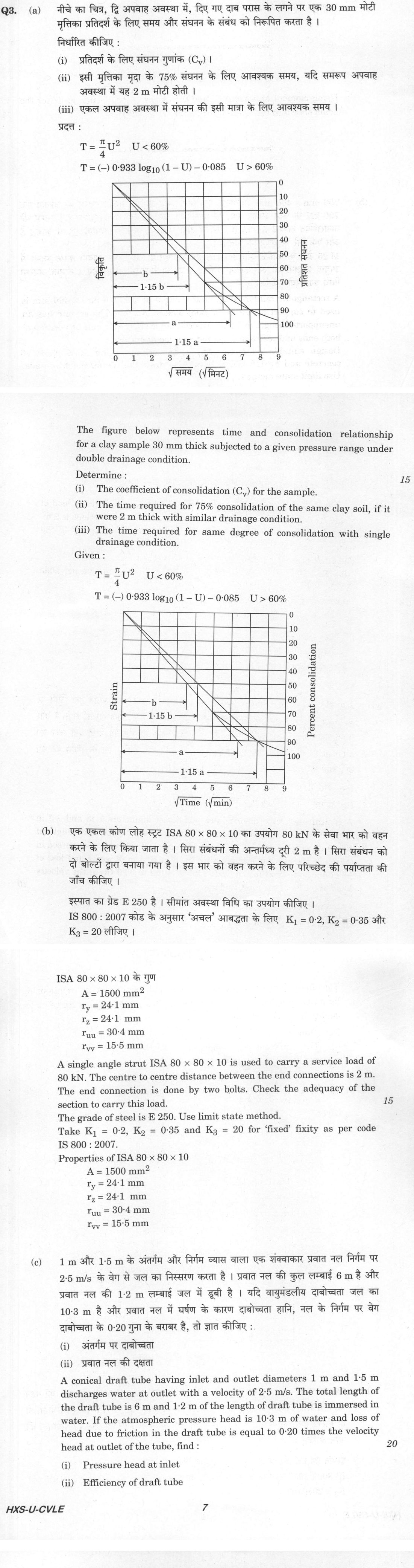
The figure this question refers to, in words
The question paper is a scan and the diagram did not survive as text. This is the figure as read from the original page — every component, value and label — so the question can be worked from the text below.
(a) A graph titled 'Strain' on the left vertical axis (uncalibrated) and 'Percent consolidation' on the right vertical axis, plotted against 'Square root of Time (square root of min)' on the horizontal axis. The horizontal axis ranges from 0 to 9 square root of min, with grid lines at 0, 1, 2, 3, 4, 5, 6, 7, 8, 9. The right vertical axis (Percent consolidation) ranges from 0 to 100%, marked in increments of 10 at 0, 10, 20, 30, 40, 50, 60, 70, 80, 90, 100. A consolidation curve starts at (0, 0), curves downward through approximately (3, 40), (4.7, 70), (6, 85), and flattens out around 90-100% consolidation at square root of time between 7 and 9. Taylor's square root of time fitting construction is shown: a straight tangent line is drawn from the origin (0, 0) through the initial linear portion of the curve, intersecting the horizontal line at 60% consolidation at a distance 'b' from the vertical axis, and intersecting the line at 90% consolidation at a distance 'a' from the vertical axis (at square root of time approximately 6.3). A second line is drawn from the origin with abscissae 1.15 times those of the tangent line: at 60% consolidation, the distance is labelled '1.15 b' (at square root of time approximately 4.15); at 90% consolidation, the distance is labelled '1.15 a' (at square root of time approximately 7.25). This 1.15-line intersects the laboratory consolidation curve at 90% consolidation, indicating square root of t_90 = 7.25 square root of min (corresponding to the vertical projection from the intersection point to the horizontal axis between 7 and 8, specifically at 7.25).
(b) Two diagrams are provided: sign conventions and a beam loading diagram.
- Sign Conventions:
- Positive Shear Force (+ V): Represented by a rectangular beam element labelled '+ V', with a downward vertical arrow on its left face and an upward vertical arrow on its right face.
- Positive Bending Moment (+ M): Represented by a rectangular beam element labelled '+ M', with a clockwise curved arrow on its left face and a counter-clockwise curved arrow on its right face (sagging moment convention).
- Beam Loading Diagram: A horizontal beam of total length 6.0 m with the following features from left to right:
- Point A (x = 0 m): Left free end of the beam.
- Span A to B (length = 0.5 m): Subjected to a uniformly distributed downward load of 25 kN/m.
- Point B (x = 0.5 m): Pinned (hinged) support.
- Span B to C (length = 1.0 m): Unloaded.
- Point C (x = 1.5 m): Subjected to a concentrated clockwise moment of 300 kN-m, marked with a dot labelled '• C'.
- Span C to D (length = 2.0 m): Unloaded.
- Point D (x = 3.5 m): Subjected to a concentrated downward vertical load of 50 kN, marked with a dot labelled '• D'.
- Span D to E (length = 1.5 m): Unloaded.
- Point E (x = 5.0 m): Roller support, marked with a dot labelled '• E'.
- Span E to F (length = 0.5 m): Unloaded.
- Point F (x = 5.5 m): Subjected to a concentrated downward vertical load of 40 kN, marked with a dot labelled '• F'.
- Overhang from F to the right end (length = 0.5 m): Unloaded, terminating at the right free end at x = 6.0 m.
Dimensions indicated below the beam:
- A to B: 0.5 m
- B to C: 1 m
- C to D: 2 m
- D to E: 1.5 m
- E to F: 0.5 m
- F to right end: 0.5 m
Additionally, a table is given with columns for points x: A, B, C, D, E, F, and rows for shear force V and bending moment M.
Model answer
Written by UPSC Answer Check against this question's marking rubric, to the expected length. UPSC does not publish answers for Mains — this is one way to score well, not an official key.
(a)(i) Taylor's square-root-of-time fitting method is used. From the given figure, the 1.15-line intersects the consolidation curve at 90% consolidation, giving √t₉₀ = 7.25 √min. Therefore, t₉₀ = (7.25)² = 52.5625 min = 3153.75 s. For double drainage, drainage path H = 30/2 = 15 mm = 1.5 cm. For U = 90%, Tᵥ = 0.848. Cᵥ = Tᵥ H² / t₉₀ = 0.848 × (1.5)² / 3153.75 = 6.05 × 10⁻⁴ cm²/s = 6.05 × 10⁻⁸ m²/s. Cᵥ = 6.05 × 10⁻⁴ cm²/s (or 6.05 × 10⁻⁸ m²/s).
(a)(ii) For U = 75% > 60%, Tᵥ = -0.933 log₁₀(1 - U) - 0.085. 1 - U = 0.25, log₁₀(0.25) = -0.60206. Tᵥ = -0.933 × (-0.60206) - 0.085 = 0.47672. Double drainage for 2 m thick clay: H = 2/2 = 1 m = 100 cm. t = Tᵥ H² / Cᵥ = 0.47672 × (100)² / (6.05 × 10⁻⁴) = 7.88 × 10⁶ s = 91.2 days. t = 91.2 days.
(a)(iii) For single drainage, H = full thickness = 2 m = 200 cm. t = Tᵥ H² / Cᵥ = 0.47672 × (200)² / (6.05 × 10⁻⁴) = 3.152 × 10⁷ s = 364.8 days ≈ 365 days. t = 364.8 days (about 365 days).
(b) Section ISA 80 × 80 × 10: A = 1500 mm², rᵥᵥ = 15.5 mm, rᵤᵤ = 30.4 mm. L = 2000 mm. As per IS 800:2007 for a single angle strut with fixed fixity: Effective length about v-v axis: Lᵥᵥ = K₁L + K₂b + K₃t = 0.2 × 2000 + 0.35 × 80 + 20 × 10 = 628 mm. λᵥᵥ = Lᵥᵥ / rᵥᵥ = 628 / 15.5 = 40.52. Effective length about u-u axis: Lᵤᵤ = 0.85 L = 1700 mm. λᵤᵤ = Lᵤᵤ / rᵤᵤ = 1700 / 30.4 = 55.92 (critical). For E250, f_y = 250 MPa, E = 2 × 10⁵ MPa. Buckling class c, α = 0.49, γ_m0 = 1.10. λ̄ = (λ / π) √(f_y / E) = (55.92 / π) √(250 / 200000) = 0.629. φ = 0.5 [1 + α(λ̄ - 0.2) + λ̄²] = 0.5 [1 + 0.49(0.629 - 0.2) + 0.629²] = 0.803. χ = 1 / (φ + √(φ² - λ̄²)) = 1 / (0.803 + √(0.803² - 0.629²)) = 0.768. f_cd = χ f_y / γ_m0 = 0.768 × 250 / 1.10 = 174.5 MPa. Design compressive strength = A f_cd = 1500 × 174.5 = 261,750 N = 261.75 kN. Design load = 1.5 × 80 = 120 kN (limit state). Since 120 kN < 261.75 kN, the section is adequate. Section is safe/adequate.
(c)(i) D₁ = 1 m, D₂ = 1.5 m, V₂ = 2.5 m/s. V₁ = V₂ (D₂/D₁)² = 2.5 × (1.5/1)² = 5.625 m/s. Velocity heads: V₁²/2g = 5.625² / (2 × 9.81) = 1.613 m; V₂²/2g = 2.5² / (2 × 9.81) = 0.319 m. h_f = 0.20 × 0.319 = 0.0637 m. Datum at outlet. Z₁ = 6 m, Z₂ = 0. Outlet submerged 1.2 m, so P₂/γ = 10.3 + 1.2 = 11.5 m (absolute). Bernoulli: P₁/γ + V₁²/2g + Z₁ = P₂/γ + V₂²/2g + Z₂ + h_f. P₁/γ = 11.5 + 0.319 + 0.0637 - 1.613 - 6 = 4.27 m (absolute). Gauge pressure head at inlet = 4.27 - 10.3 = -6.03 m (vacuum of 6.03 m). Pressure head at inlet = 4.27 m of water (absolute), or -6.03 m gauge.
(c)(ii) Efficiency of draft tube: η_d = (V₁²/2g - V₂²/2g - h_f) / (V₁²/2g) × 100 = (1.613 - 0.319 - 0.0637) / 1.613 × 100 = 76.3%. η_d = 76.3%.
What "Calculate" is asking you to do
Apply the standard formula or schedule to data the question has already supplied — a table of readings, cost records, a balance sheet — and produce the number. The method is rarely in doubt; the marks sit in the named intermediate quantities, each of which has to appear as a labelled line.
Structure that answers it
Data as given → formula or standard treatment, named → substitution → each intermediate, labelled → result with units
Where marks are lost
Omitting an intermediate the marking scheme pays for separately, or rounding at an intermediate line so the final figure drifts. In commerce and accountancy, any figure in a statement that no numbered working note supports is treated as unearned.
How this answer will be evaluated
Approach
Framework: null. (a) calculate: given > formula > substitution > result with units > interpretation | (b) calculate: given > formula > substitution > result with units > interpretation | (c) calculate: given > formula > substitution > result with units > interpretation Full marks: All parts solved with correct formulas, units, and checks; clear presentation.
Key points expected
- Extract time for 50% consolidation from graph
- Calculate Cv using T = (π/4)U² for U < 60%
- Scale time for 2m thickness using t ∝ H²
- Adjust time for single drainage (t ∝ 4H²)
- Determine effective length using K1, K2, K3
- Calculate slenderness ratio (L/r)
- Find design compressive strength from IS 800:2007
- Compare design strength with factored load
Evaluation rubric
Each sub-part is marked on its own, against the marks and word limit printed on the paper.
- (a) Determine Cv, time for 75% consolidation (2m thick), and time for single drainage. 15 marks
calculate— given → formula → substitution → result with units → interpretation
Must cover
- Extract time for 50% consolidation from graph
- Calculate Cv using T = (π/4)U² for U < 60%
- Scale time for 2m thickness using t ∝ H²
- Adjust time for single drainage (t ∝ 4H²)
Loses marks
- Confusing single and double drainage path lengths
- Incorrect scaling of time with thickness
Earns more
- Correct identification of double drainage path length
- Use of log formula for U > 60% if applicable
- Clear unit conversion (mm to m)
Extra mark
- Neatly labelled consolidation curve sketch
- (b) Check adequacy of ISA 80x80x10 strut for 80 kN load using limit state method. 15 marks
calculate— given → formula → substitution → result with units → interpretation
Must cover
- Determine effective length using K1, K2, K3
- Calculate slenderness ratio (L/r)
- Find design compressive strength from IS 800:2007
- Compare design strength with factored load
Loses marks
- Using working stress method instead of limit state
- Ignoring end connection fixity factors
Earns more
- Correct application of IS 800:2007 buckling curve
- Explicit statement of partial safety factor
- Check for local buckling if required
Extra mark
- Reference to specific IS 800:2007 clause
- (c) Find pressure head at inlet and efficiency of the conical draft tube. 20 marks
calculate— given → formula → substitution → result with units → interpretation
Must cover
- Apply Bernoulli's equation between inlet and outlet
- Calculate velocity head at outlet (v²/2g)
- Determine friction loss (0.20 × velocity head)
- Calculate efficiency as (H - hf) / H
Loses marks
- Incorrect sign convention in Bernoulli's equation
- Ignoring friction loss in efficiency calculation
Earns more
- Correct application of atmospheric pressure head
- Clear distinction between submerged and free discharge
- Accurate calculation of velocity head
Extra mark
- Sketch of draft tube with labelled heads
Practice this exact question
Write your answer and it is marked point by point against the model answer above — what you covered, what you missed, what you got wrong.
Evaluate my answer →More from Civil Engineering 2021 Paper I
- Q1 (a) Determine the forces in members AC, DE and GH of the truss loaded and supported as sh…
- Q2 (a) Using moment area method, find the slopes and deflection at 'B' for the beam shown in…
- Q3 (a) The figure below represents time and consolidation relationship for a clay sample 30…
- Q4 (a) Determine the maximum tensile force in member DI of the truss shown below due to the…
- Q5 (a) A circular log of weight 1000 N and radius 18 cm is supported by a pair of brackets,…
- Q6 (a) A submarine can be assumed to have cylindrical shape with rounded nose. Assuming its…